Marquee PCBs
 For the marquee, I was assigned the letter ‘i’. I designed the letter board and changed the sensor board since my last post. The new sensor board is based on Andy’s; I only changed the sensor headers from 2 pins to 3 to fit a potentiometer.
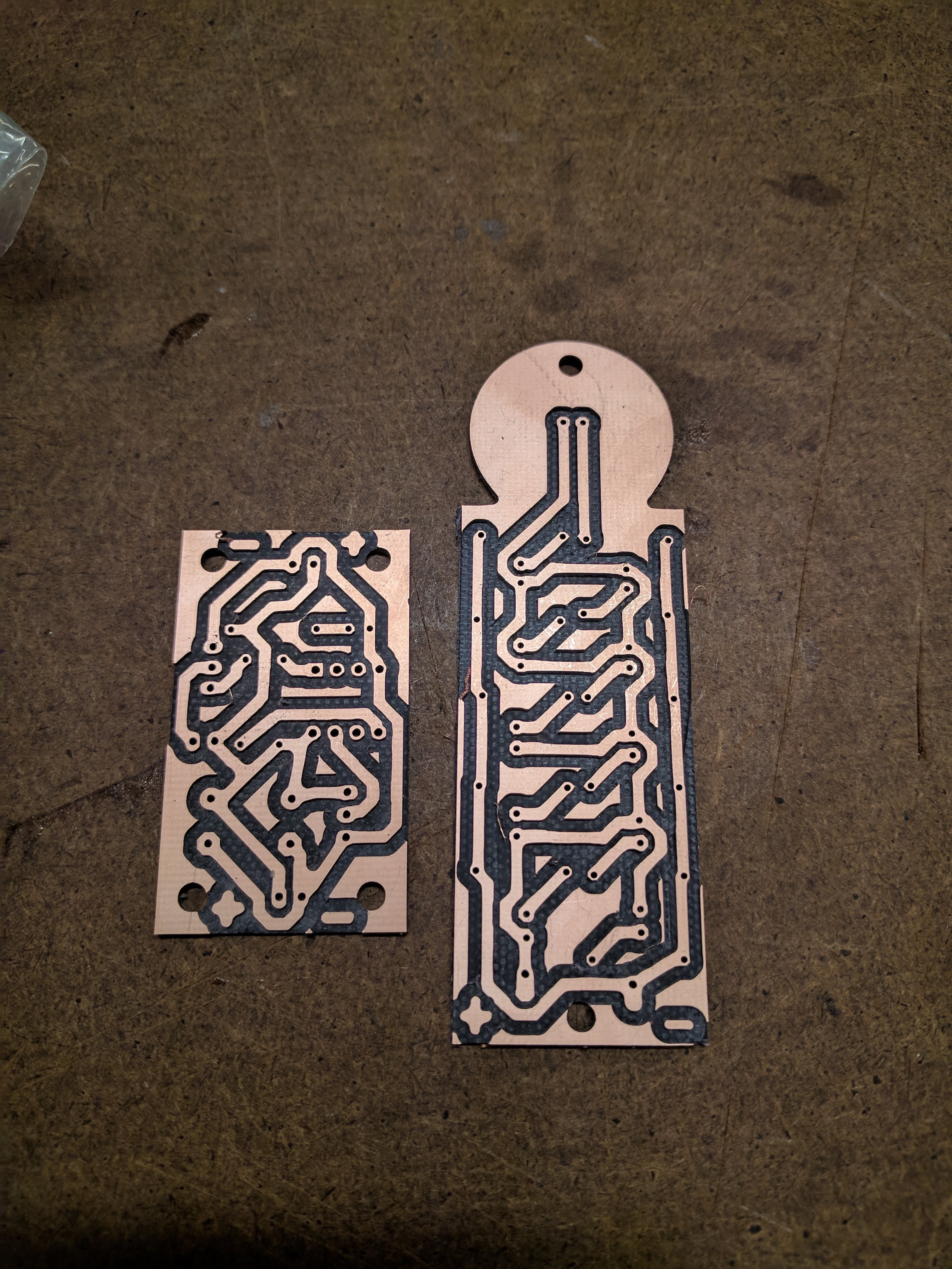
Boards after milling
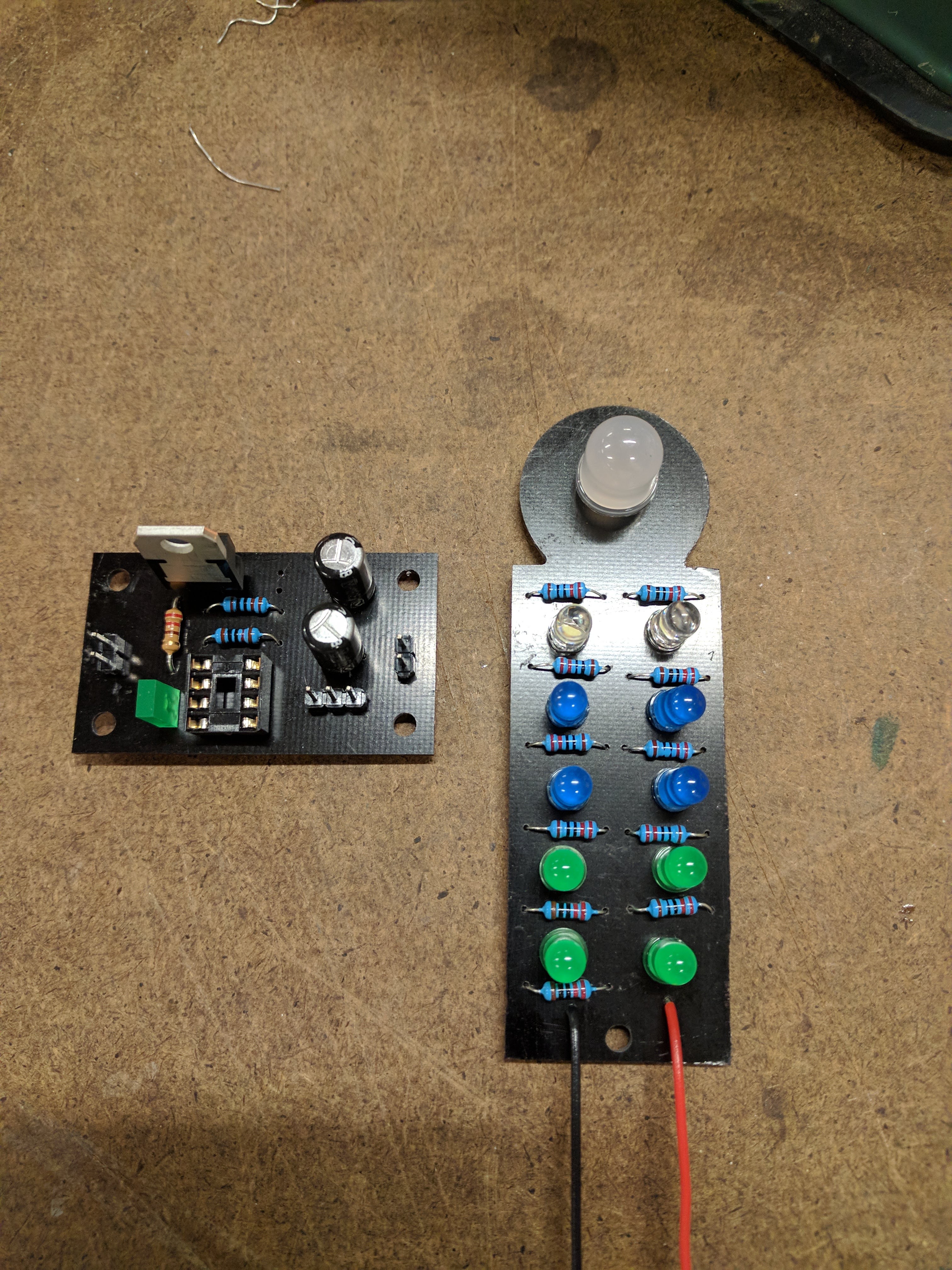
After soldering on components
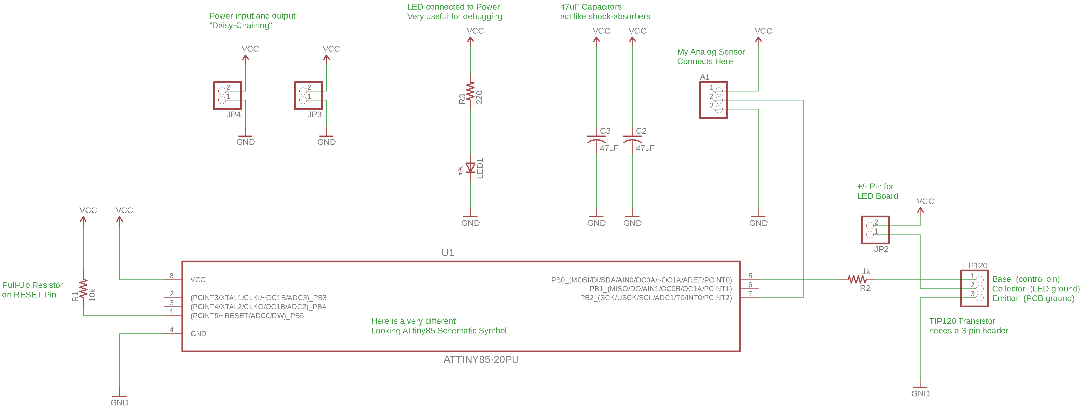
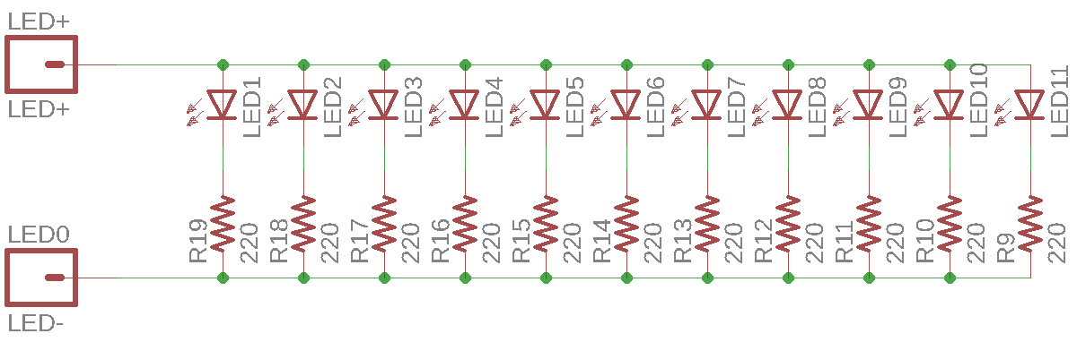
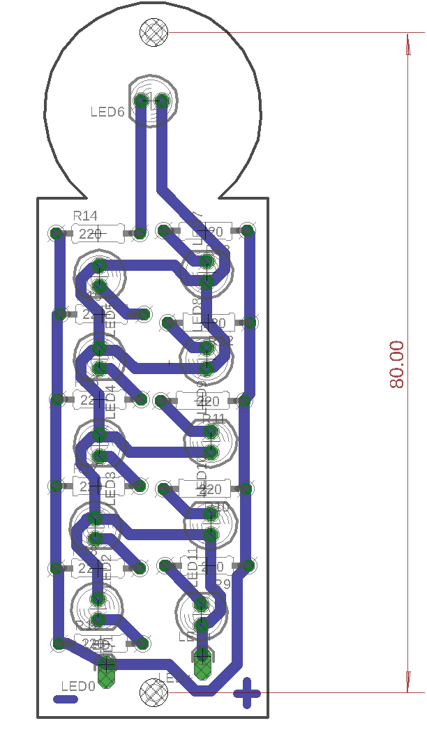
Schematics and Board Designs
ATtiny85 and sensor board
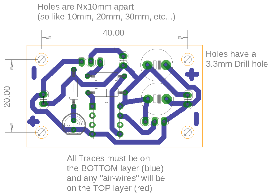
‘i’ board
Code
I programmed the ATtiny85 to make the leds pulse. I changed the interaction so that the potentiometer adjusts the pulse rate of the leds.
/*
  Changes speed of fading led based on potentiometer reading
*/

int led = 0;           // the PWM pin the LED is attached to
int brightness = 0;    // how bright the LED is
int potValue = 0; // value from potentiometer
int fadeAmount = 1;    // how many points to fade the LED by
int delayTime;

void setup() {
  pinMode(A1, INPUT);
  pinMode(led, OUTPUT);
}

void loop() {

  // set the brightness of pin 9:
  analogWrite(led, brightness);

  // change the brightness for next time through the loop:
  potValue = analogRead(A1);
  delayTime = map(potValue, 0, 1023, 30, 0);       //map pot value to a fade delay
  brightness = brightness + fadeAmount;

  // reverse the direction of the fading at the ends of the fade:
  if (brightness <= 0 || brightness >= 255) {
    fadeAmount = -fadeAmount;
  }
  // wait to see the dimming effect
  delay(delayTime);
}
Video Documentation of Interaction####
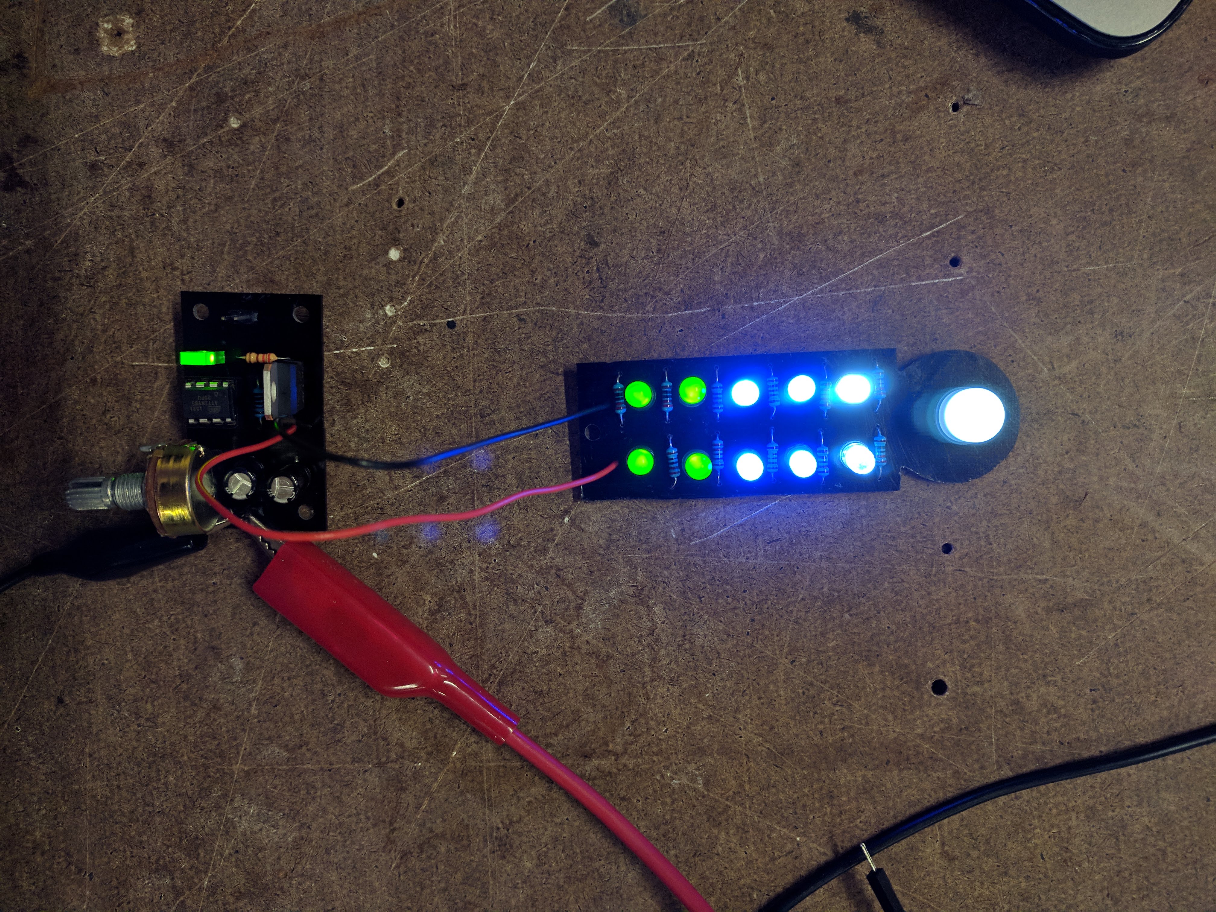
It works!!
Written on February 17, 2018