Digital Input and Output
I began by completing the digital input and output lab on the ITP PComp syllabus.
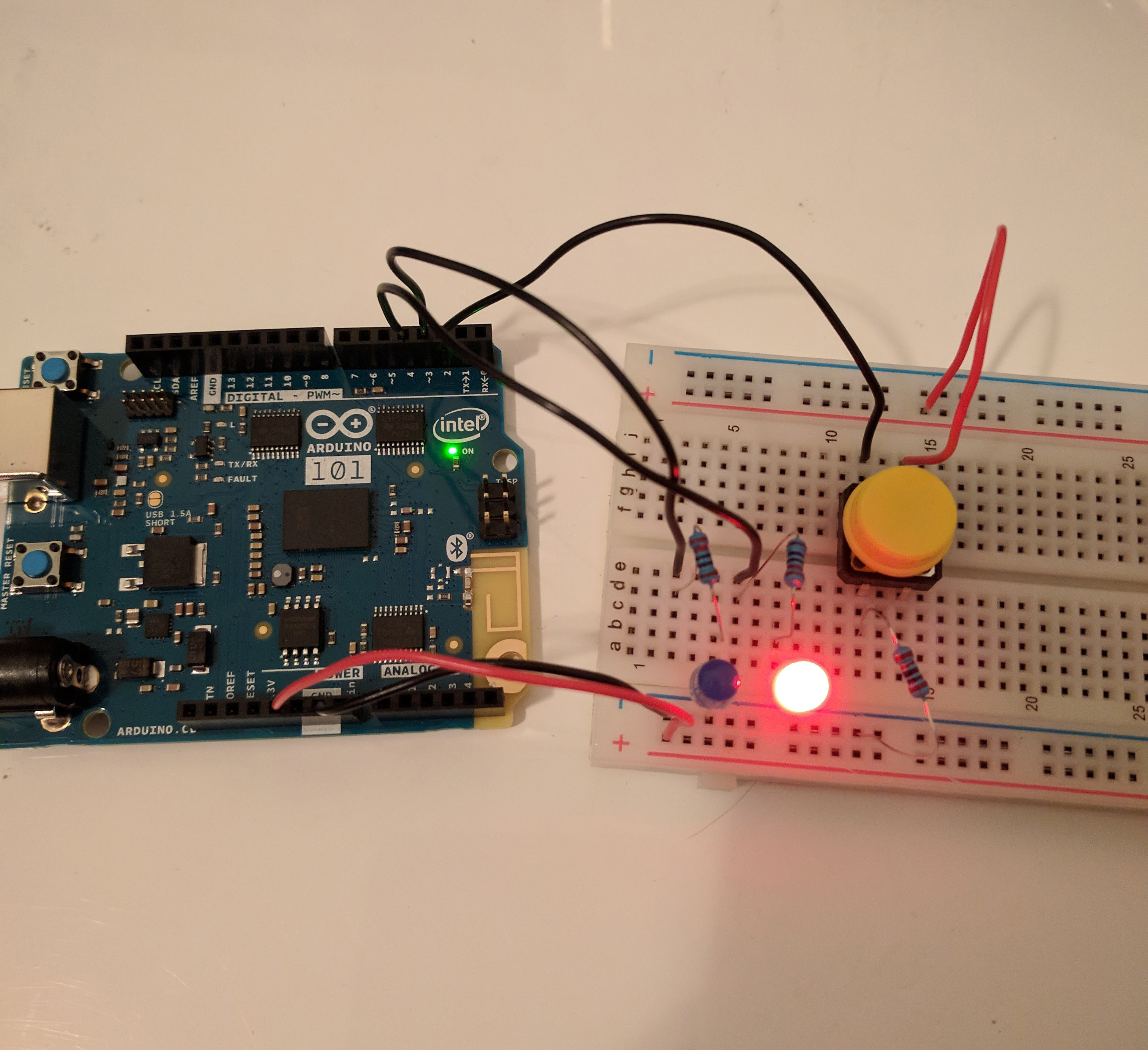
This circuit changes which LED lights up based on whether the switch is pushed down or not. I combined this idea with the Arduino tutorial ‘fade’ example. In this example, an increasing and decreasing brightness value is passed to an LED, fading it brighter and then dimmer.
My application has 2 switches and 1 LED. When one switch is pressed, the LED gets brighter (max at brightness value 255). When the other switch is pressed, the LED gets dimmer (min at brightness value 0).
Circuit and connections with LED shown at max brightness:
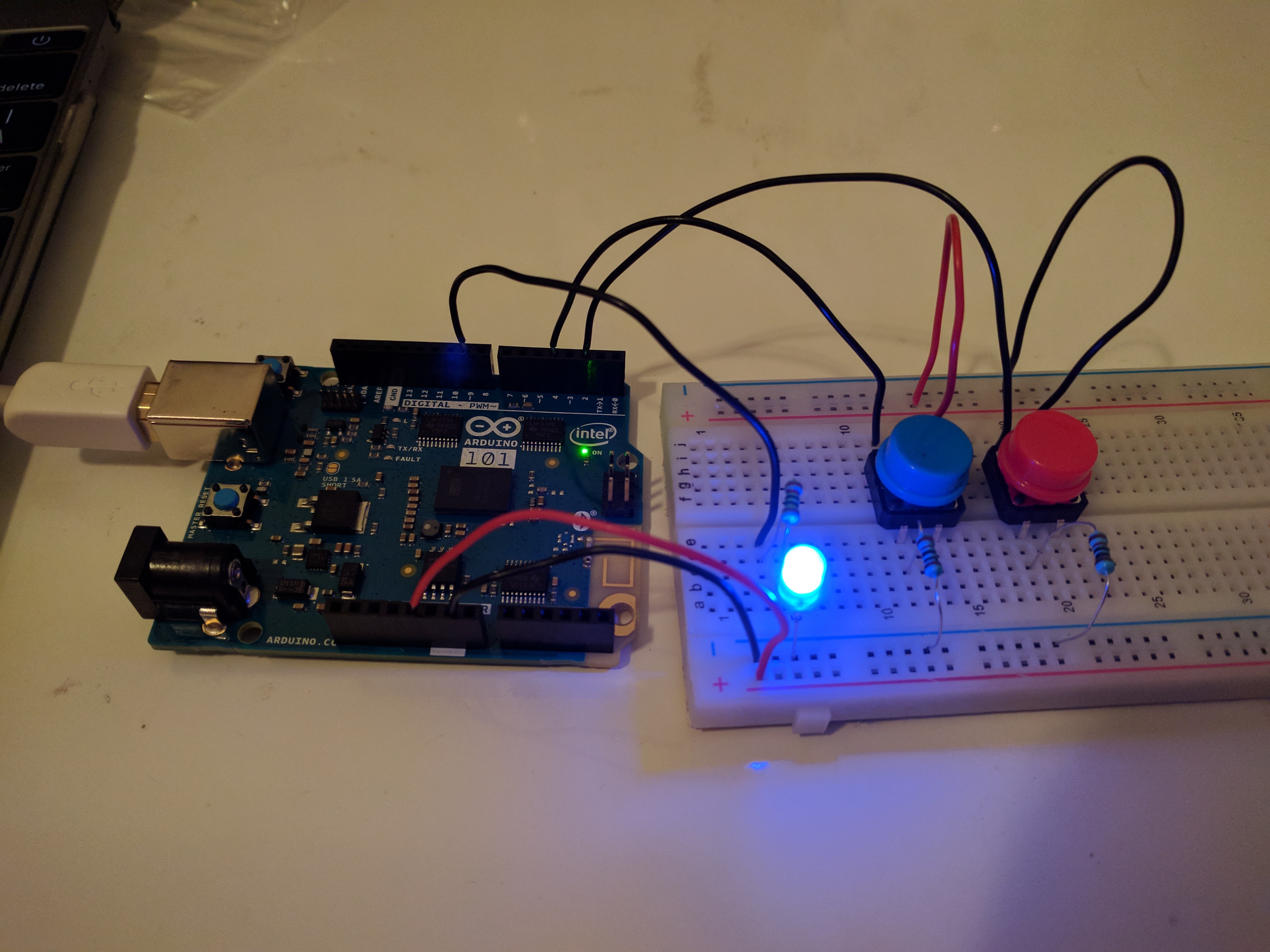
The LED is connected at pin 9.
Blue switch1 (brightens) is connected at pin 4.
Red switch2 (dims) is connected at pin 2.
LED brightening while holding down switch1:
LED dimming while holding down switch2:
Full code:
/*
  adapted from arduino fade example and ITP PComp digital input lab
*/

// pin switches are attached to
int switch1 = 4;	// blue in picture
int switch2 = 2;	// red in picture

int led1 = 9;           // the PWM pin the LED is attached to

int brightness = 0;    // how bright the LED is
int fadeAmount = 5;    // how many points to fade the LED by

// the setup routine runs once when you press reset:
void setup() {
  // declare LED outputs
  pinMode(led1, OUTPUT);

  // declare switch inputs
  pinMode(switch1, INPUT);
  pinMode(switch2, INPUT);
}

// the loop routine runs over and over again forever:
void loop() {
    // set the brightness of LEDs
    analogWrite(led1, brightness);

  if (digitalRead(switch1) == LOW) {
    // increase brightness
    if(brightness <= 250){
      brightness = brightness + fadeAmount;
     delay(30);
    }
  }

  if (digitalRead(switch2) == LOW) {
    // decrease brightness
    if(brightness >= 5){
      brightness = brightness - fadeAmount;
      delay(30);
    }
  }
}