This project was a combination of my finals for Homemade Hardware and Electronic Rituals. While reading personal posts on instagram, I realized that I often commented the phrase ‘sending love’ when I wanted to show my support for that person. In a way, through our connections on social media, we give each other protection and support. An amulet is an item that traditionally gives its wearer protection and good luck. I wanted to make an amulet that received its power through the internet.
I made a battery powered earing with neopixels. My goal for this assignment was to learn how to use surface mount components so I kept the design and functionality simple.
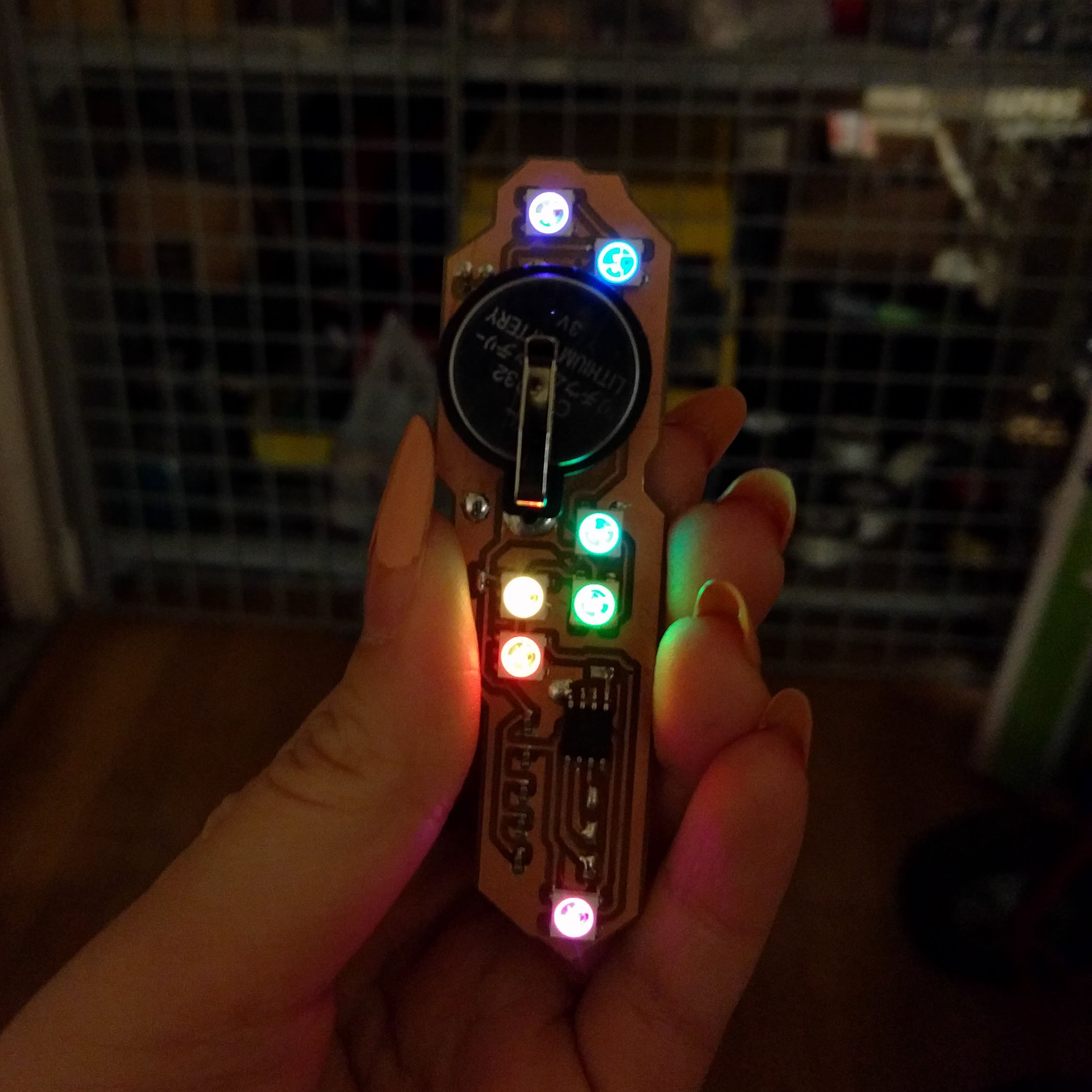
I used Adafruit’s example code for neopixels and adapted it for my needs. I turned the brightness down since I’m only powering it with a 3V coin cell battery.
#include <Adafruit_NeoPixel.h>
intpin=3;intlen=7;Adafruit_NeoPixelstrip=Adafruit_NeoPixel(len,pin,NEO_GRB+NEO_KHZ800);voidsetup(){strip.begin();strip.show();strip.setBrightness(20);}voidloop(){rainbowCycle(20);}/*
from adafruit's strandtest example
*/// Slightly different, this makes the rainbow equally distributed throughoutvoidrainbowCycle(uint8_twait){uint16_ti,j;for(j=0;j<256*5;j++){// 5 cycles of all colors on wheelfor(i=0;i<strip.numPixels();i++){strip.setPixelColor(i,Wheel(((i*256/strip.numPixels())+j)&255));}strip.show();delay(wait);}}// Input a value 0 to 255 to get a color value.// The colours are a transition r - g - b - back to r.uint32_tWheel(byteWheelPos){WheelPos=255-WheelPos;if(WheelPos<85){returnstrip.Color(255-WheelPos*3,0,WheelPos*3);}if(WheelPos<170){WheelPos-=85;returnstrip.Color(0,WheelPos*3,255-WheelPos*3);}WheelPos-=170;returnstrip.Color(WheelPos*3,255-WheelPos*3,0);}
Process
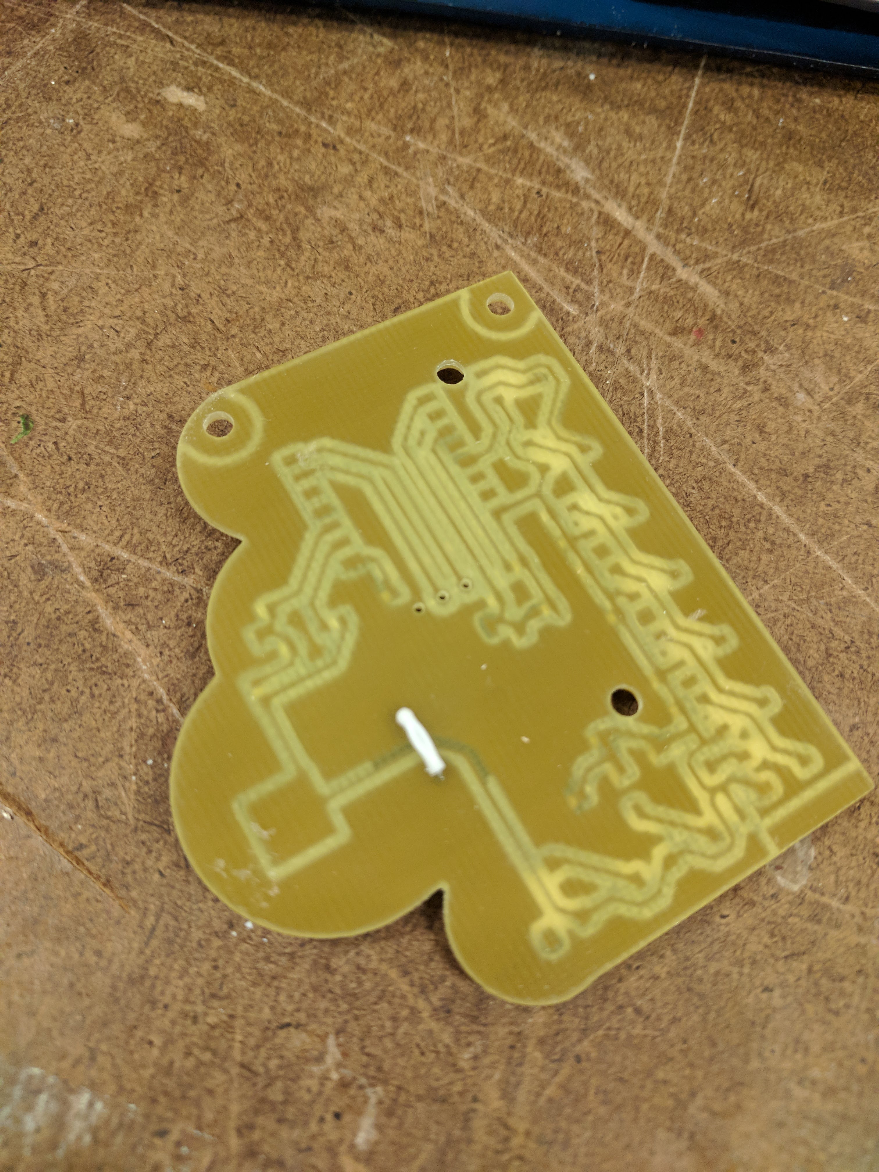
I had to remill the board several times while making the dimensions larger so that the ground plane would not get disconnected.
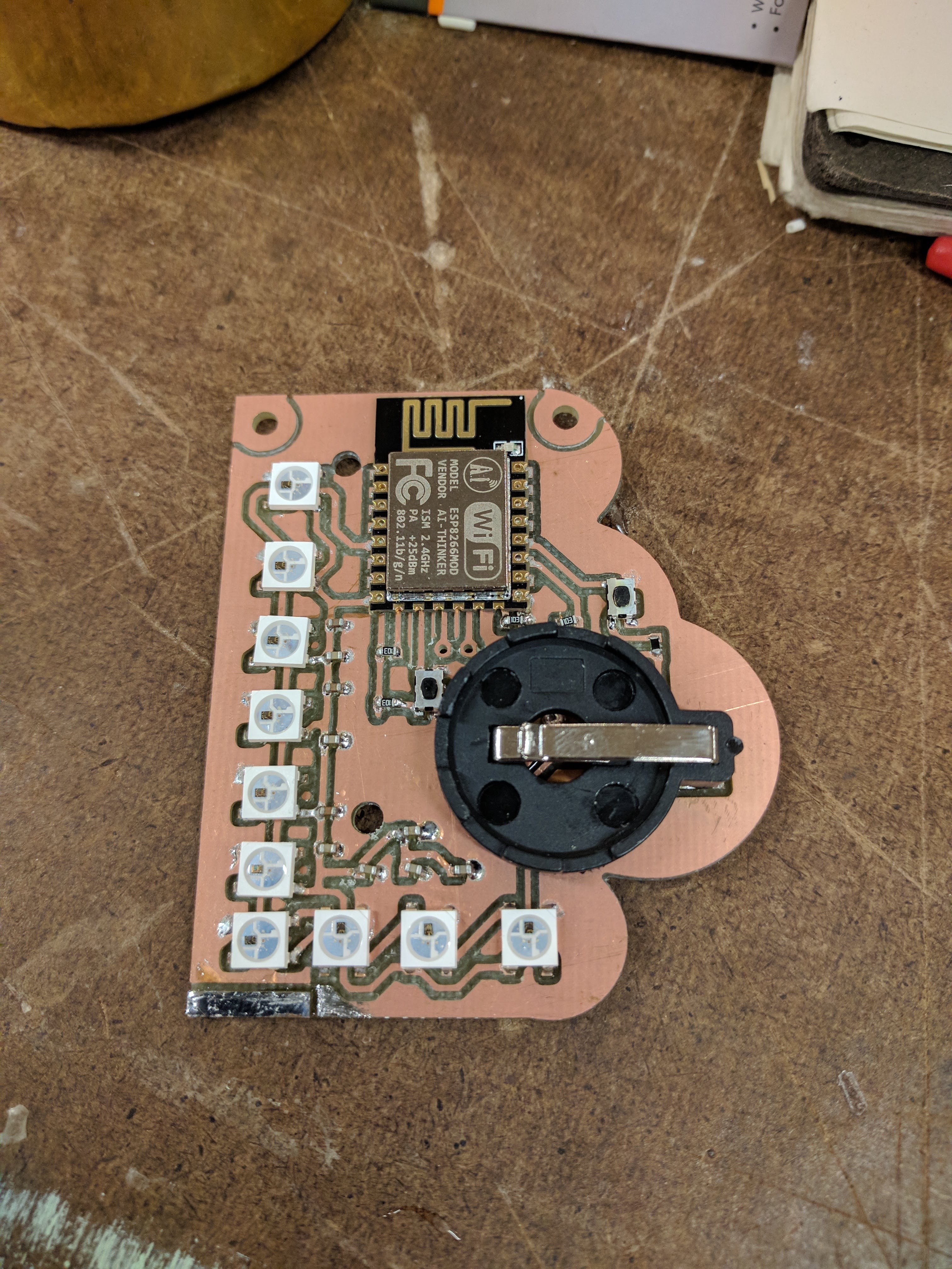
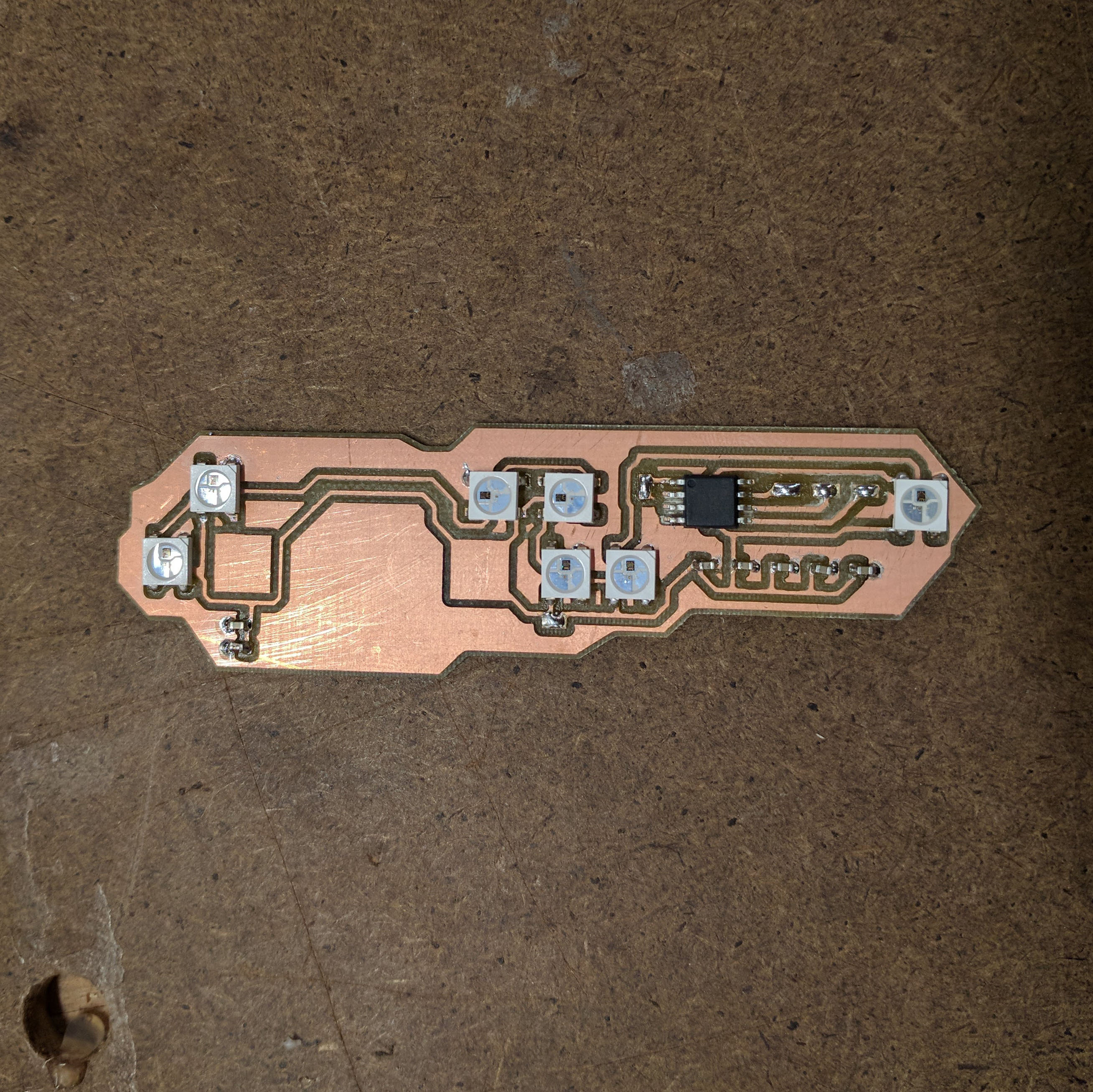
After placing surface mount components and reflow:
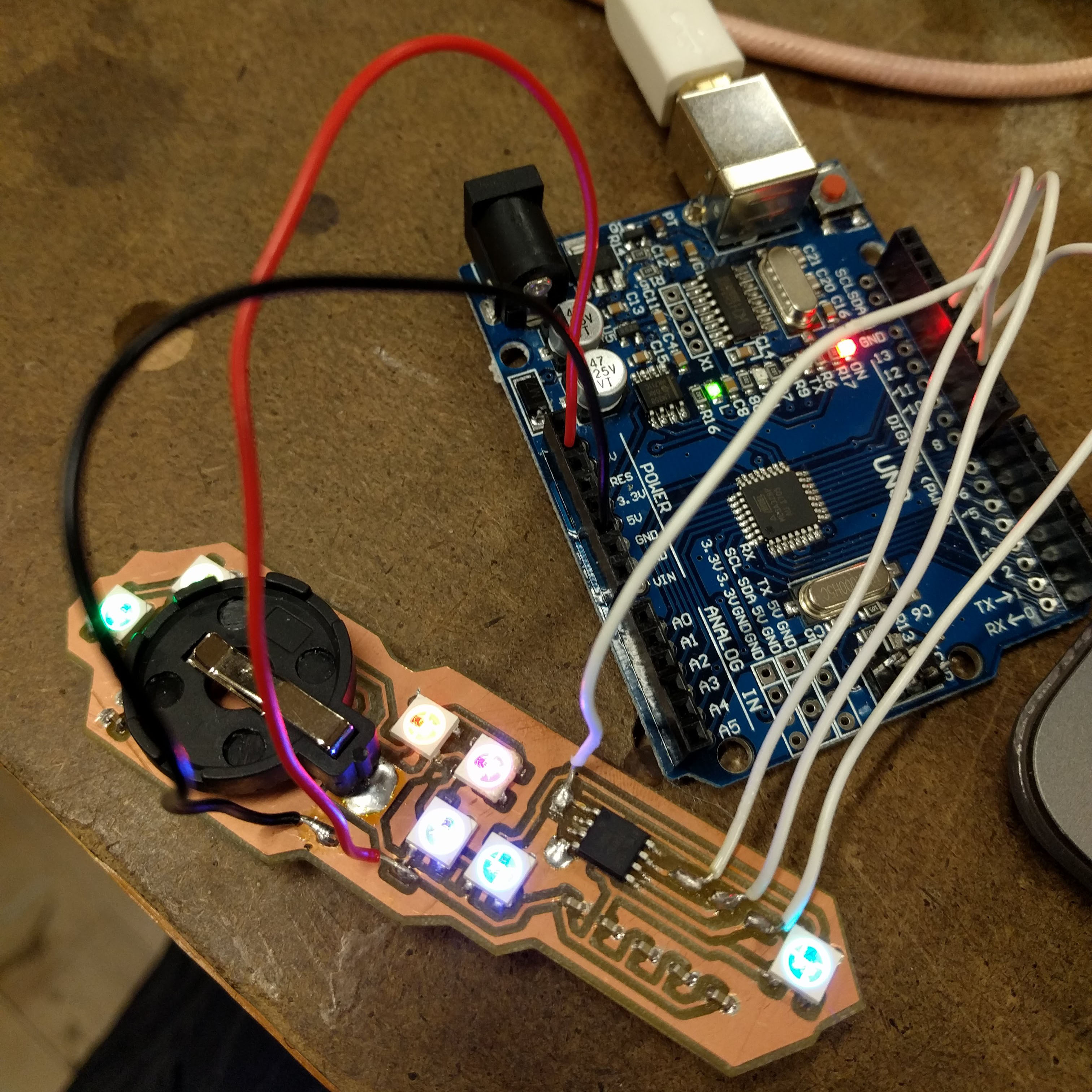
I left pads to solder wires to that connect to my Arduino Uno to program the ATTiny85. While programming, something went wrong and I could no longer get a device signature from my ATtiny85. I ended up replacing it with another one which worked.
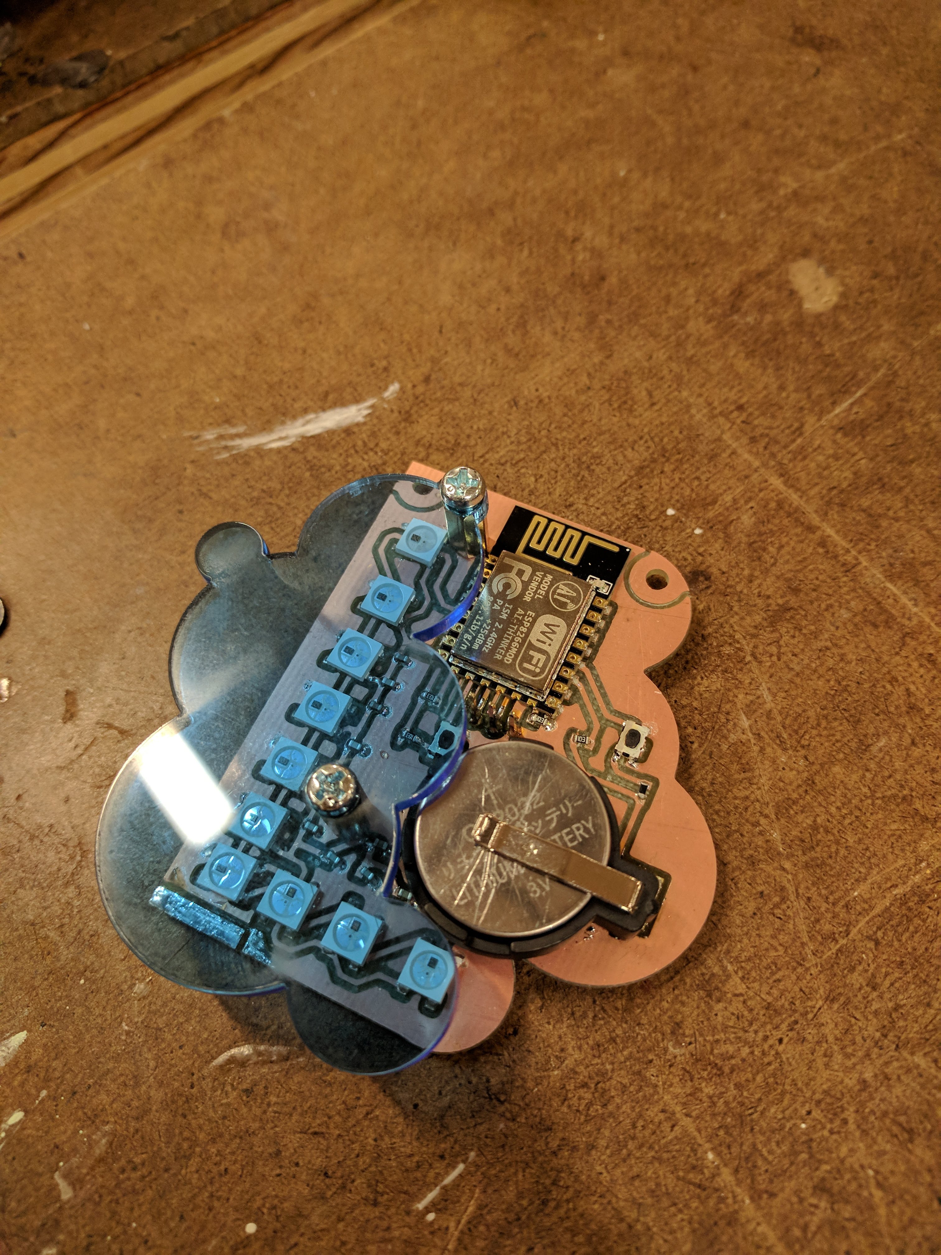
Mistakes in Board Design
After receiving the battery holders, I found out that they are different from the part I used in the board design. The ground pin is on the side and not in the center (as it is in the board design file). I soldered a wire to connect the ground plane in the center to the side plane which was not connected to anything. I then soldered the battery holder on top of that.
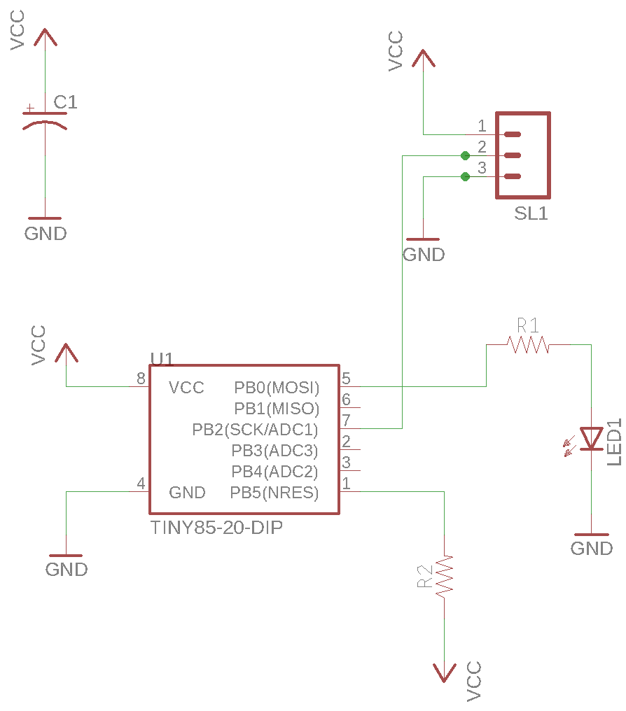
While programming, I realized I also made a mistake in the board design and forgot to add an external pull-up resistor to VCC on the reset pin of the ATTiny85. I also did not add a resistor before my first neopixel which is recommended by Adafruit.
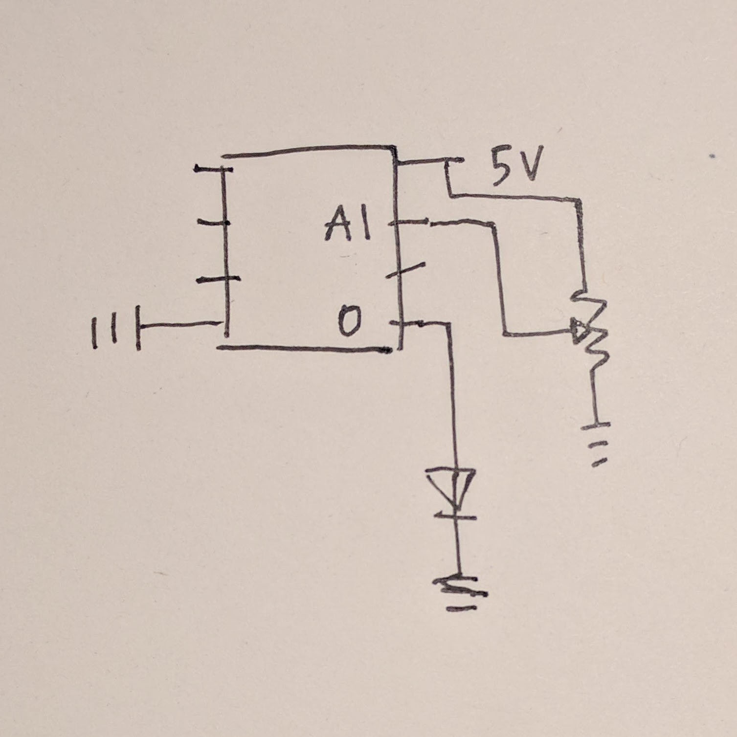
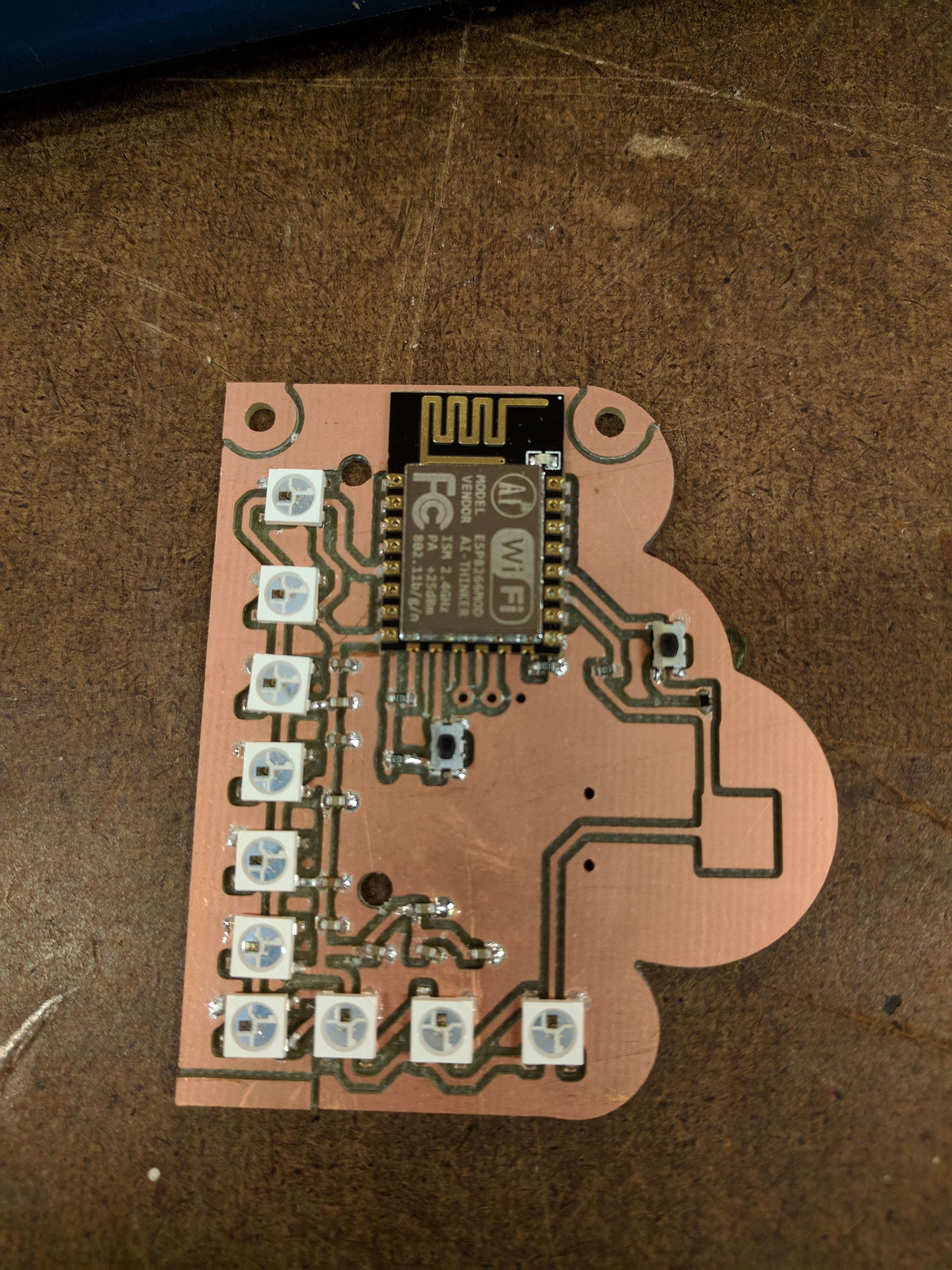
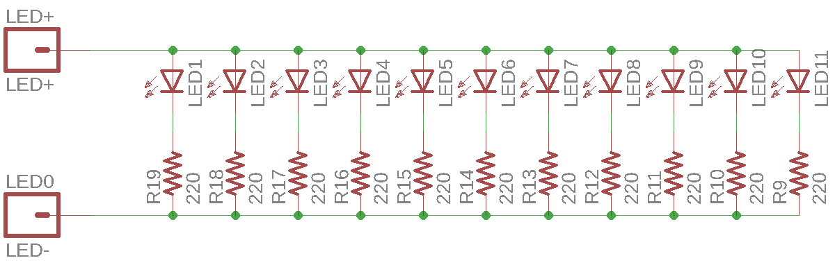
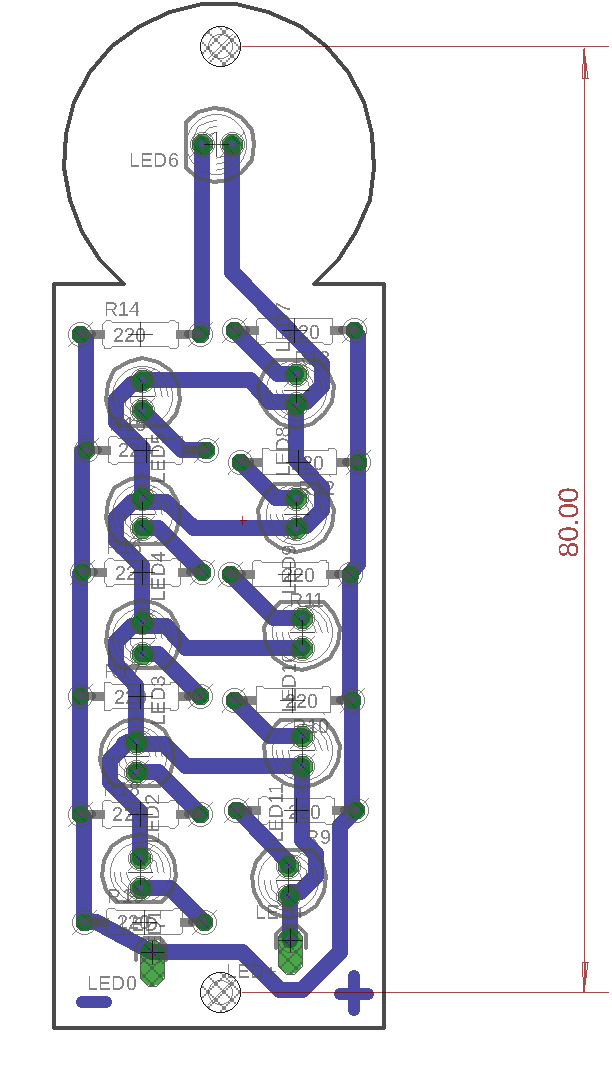
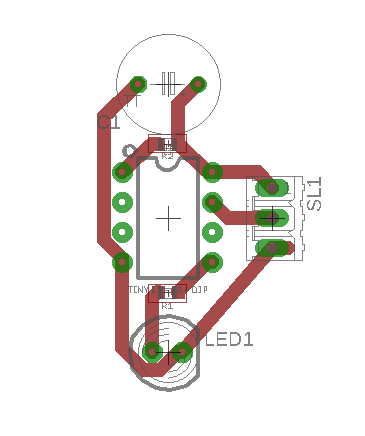
For the marquee, I was assigned the letter ‘i’. I designed the letter board and changed the sensor board since my last post. The new sensor board is based on Andy’s; I only changed the sensor headers from 2 pins to 3 to fit a potentiometer.
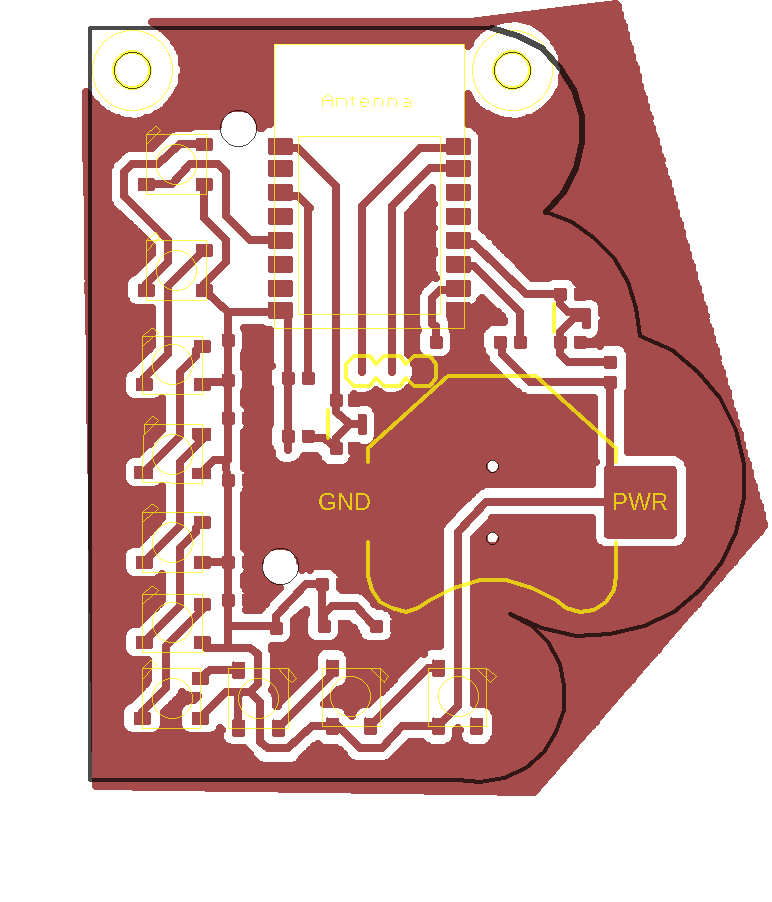
Boards after milling
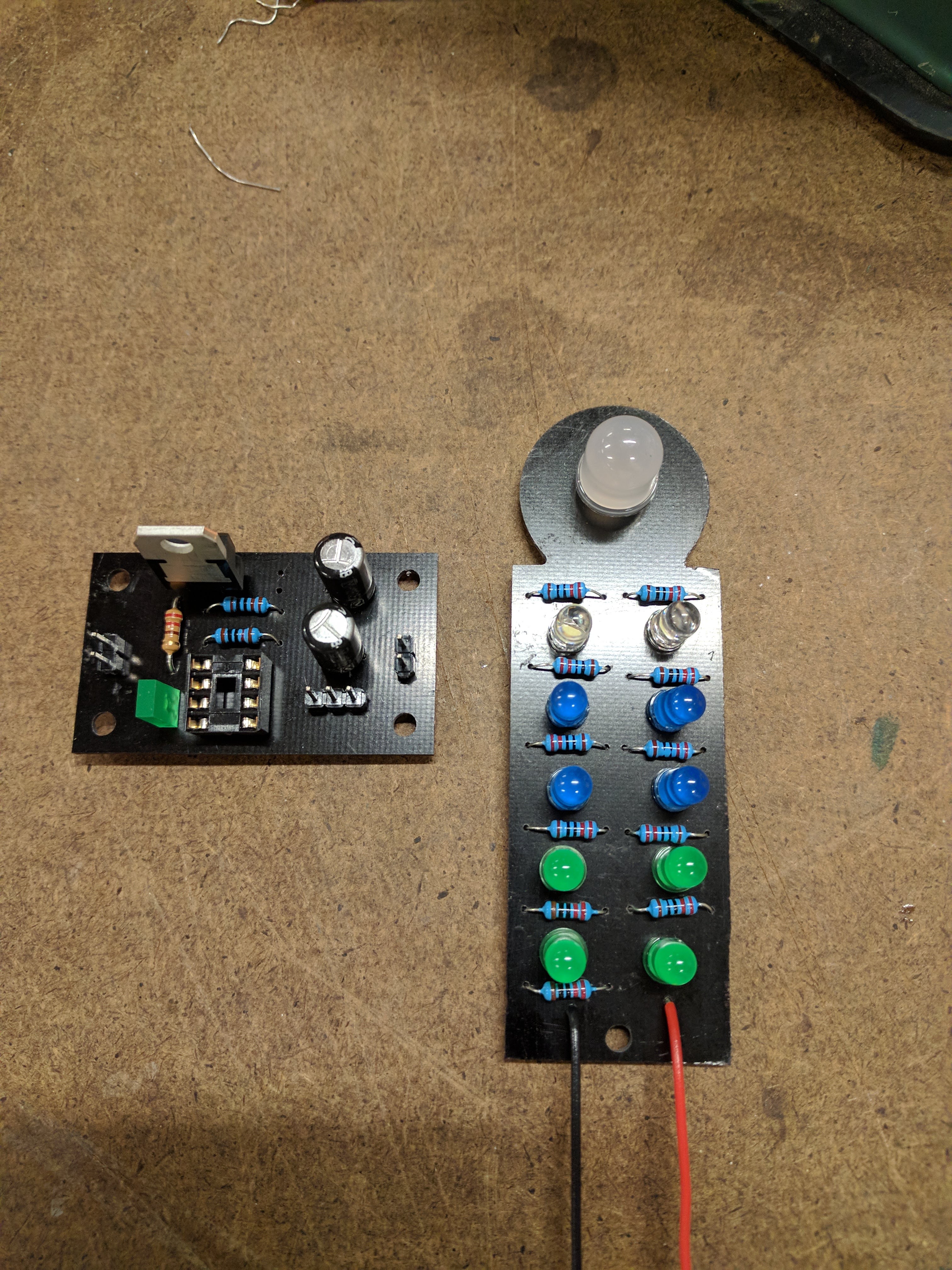
After soldering on components
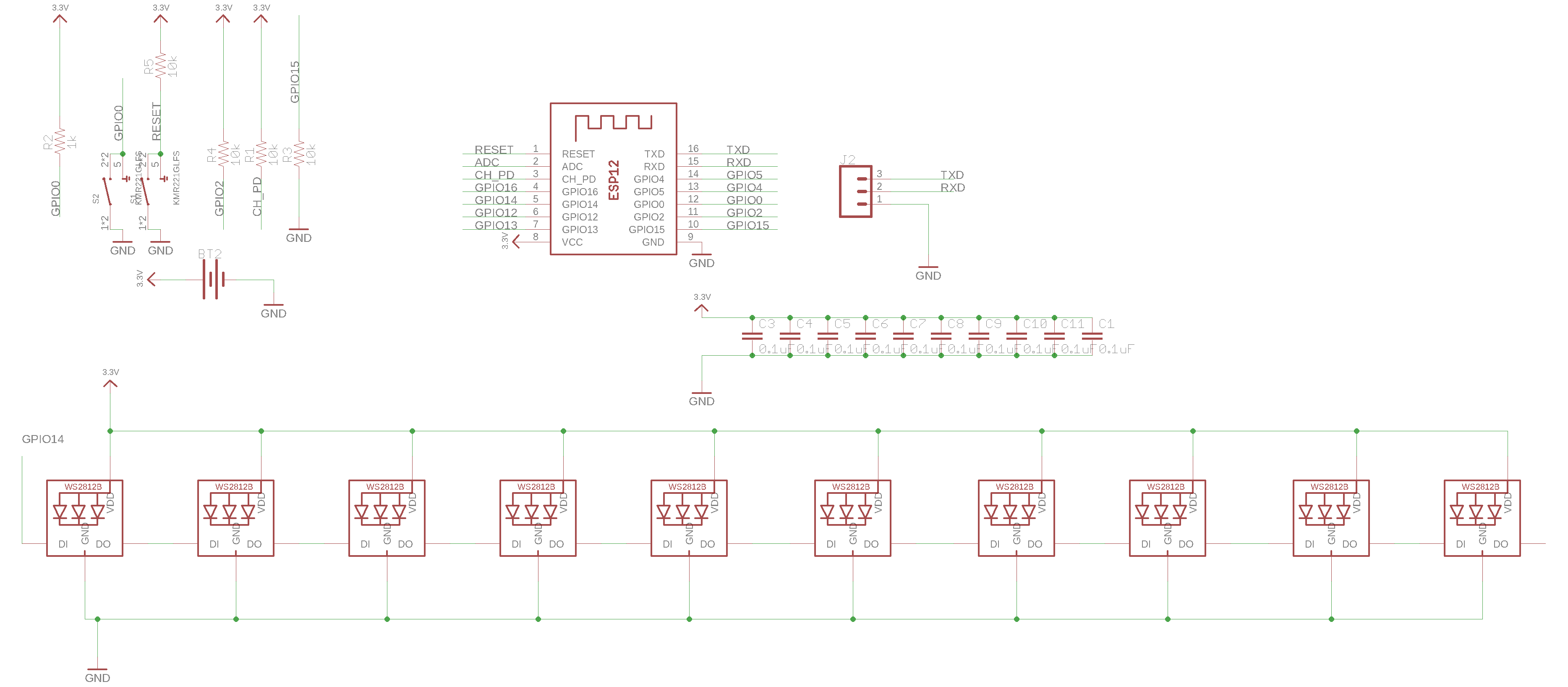
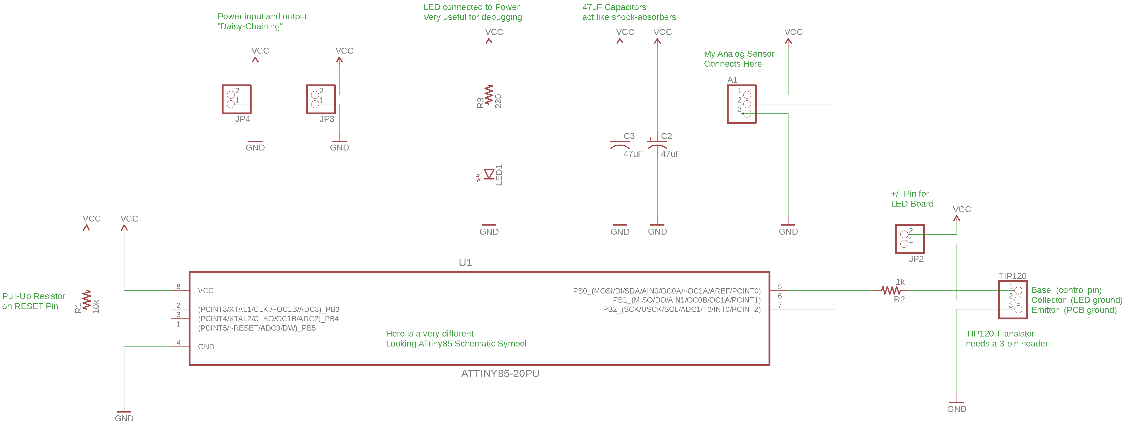
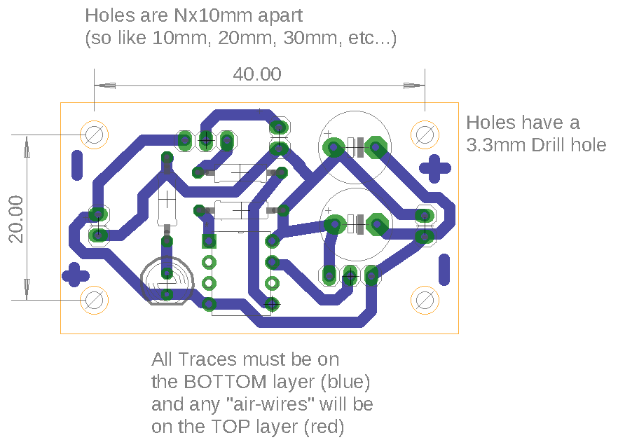
Schematics and Board Designs
ATtiny85 and sensor board
‘i’ board
Code
I programmed the ATtiny85 to make the leds pulse. I changed the interaction so that the potentiometer adjusts the pulse rate of the leds.
/*
Changes speed of fading led based on potentiometer reading
*/intled=0;// the PWM pin the LED is attached tointbrightness=0;// how bright the LED isintpotValue=0;// value from potentiometerintfadeAmount=1;// how many points to fade the LED byintdelayTime;voidsetup(){pinMode(A1,INPUT);pinMode(led,OUTPUT);}voidloop(){// set the brightness of pin 9:analogWrite(led,brightness);// change the brightness for next time through the loop:potValue=analogRead(A1);delayTime=map(potValue,0,1023,30,0);//map pot value to a fade delay brightness=brightness+fadeAmount;// reverse the direction of the fading at the ends of the fade:if(brightness<=0||brightness>=255){fadeAmount=-fadeAmount;}// wait to see the dimming effectdelay(delayTime);}
 I made a battery powered earing with neopixels. My goal for this assignment was to learn how to use surface mount components so I kept the design and functionality simple.
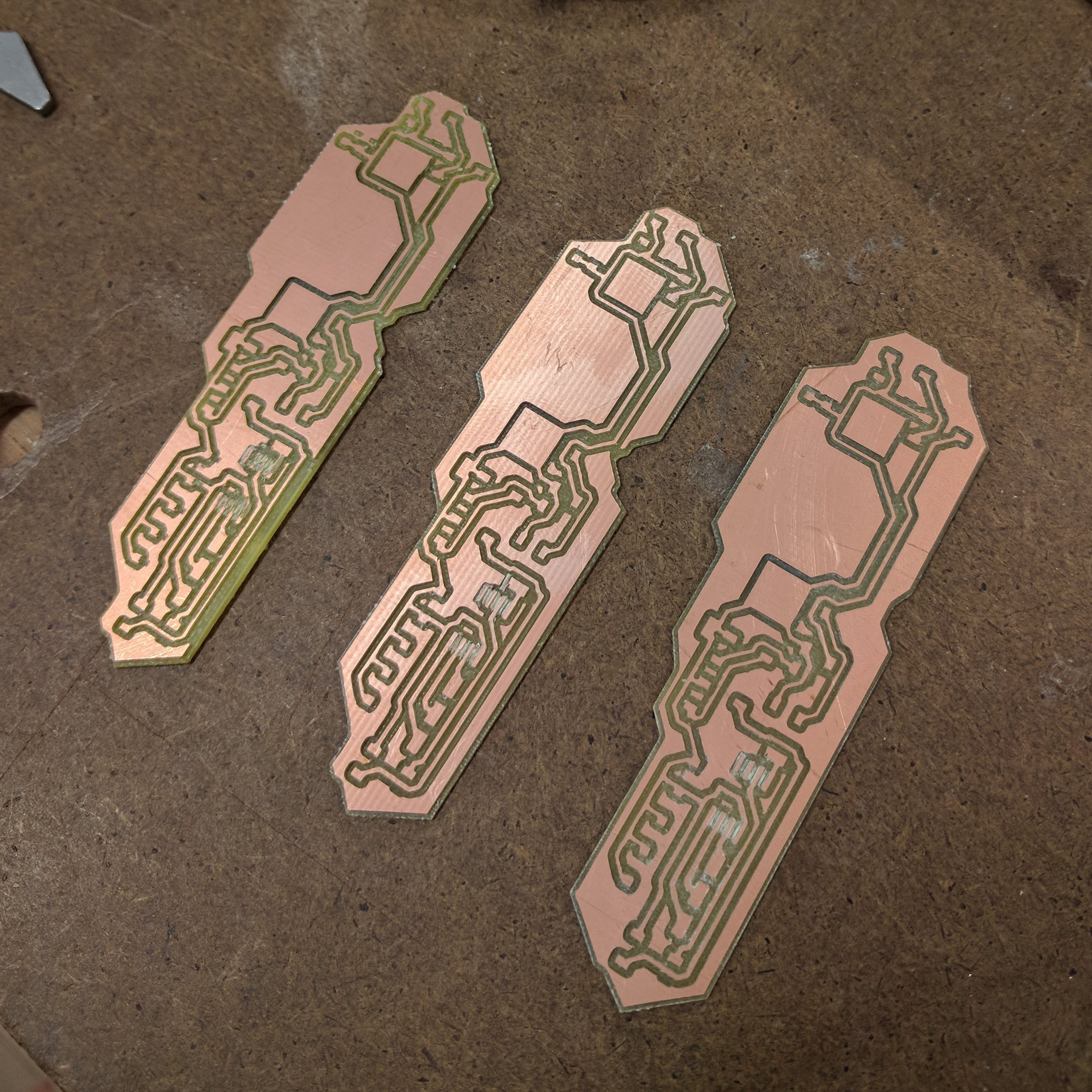
 For the marquee, I was assigned the letter ‘i’. I designed the letter board and changed the sensor board since my last post. The new sensor board is based on Andy’s; I only changed the sensor headers from 2 pins to 3 to fit a potentiometer.
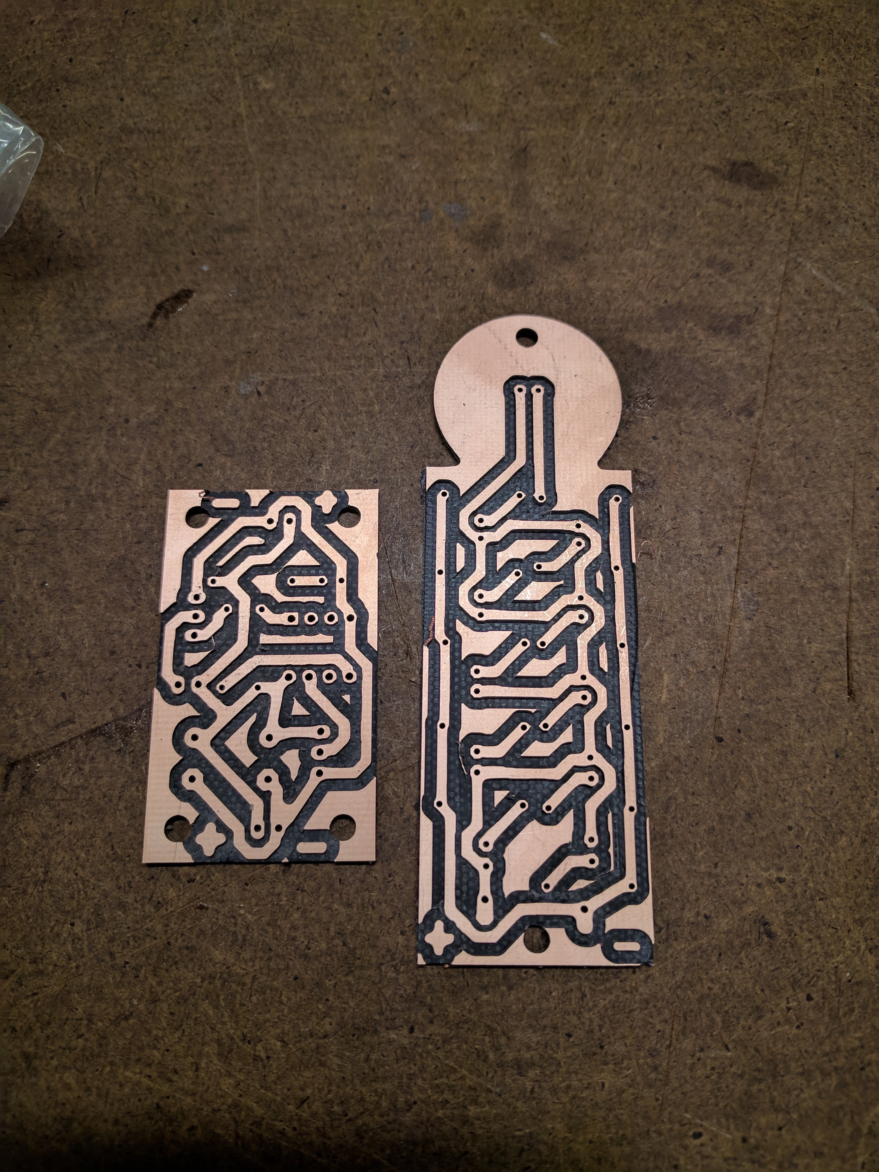
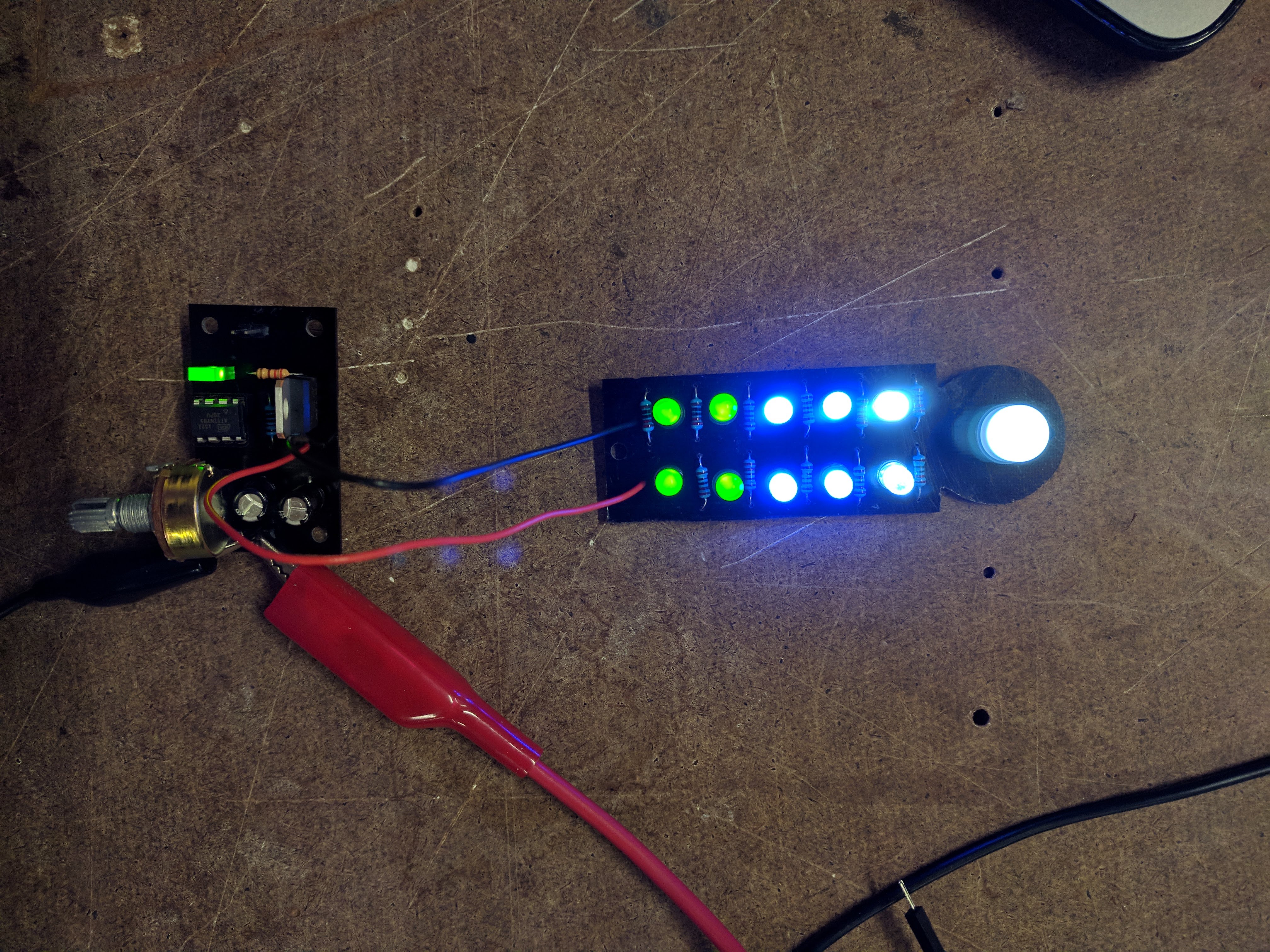
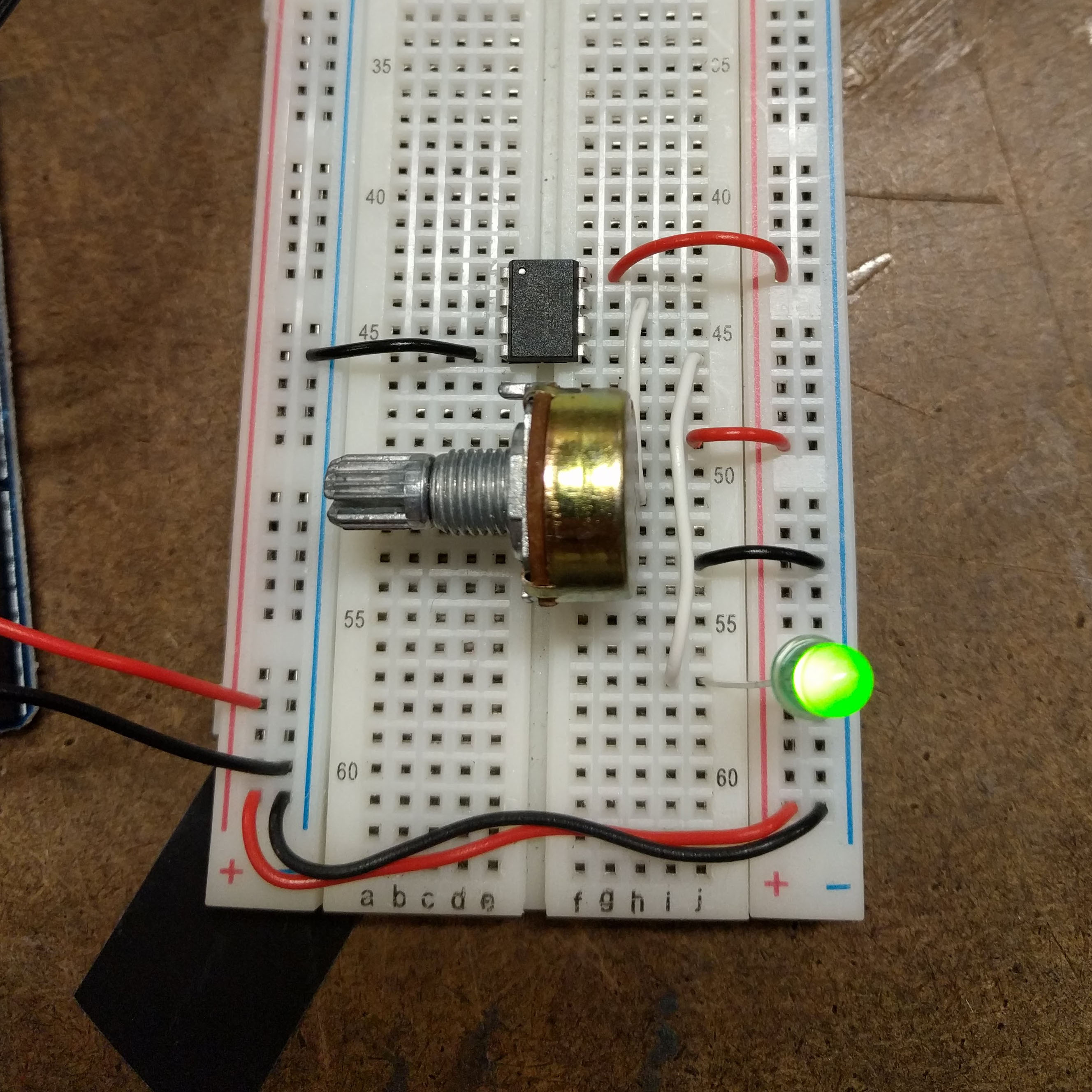 Made a simple sensor that dims the led through potentiometer value.