Filed Under #introfab
Inspiration
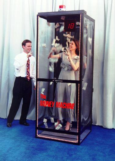
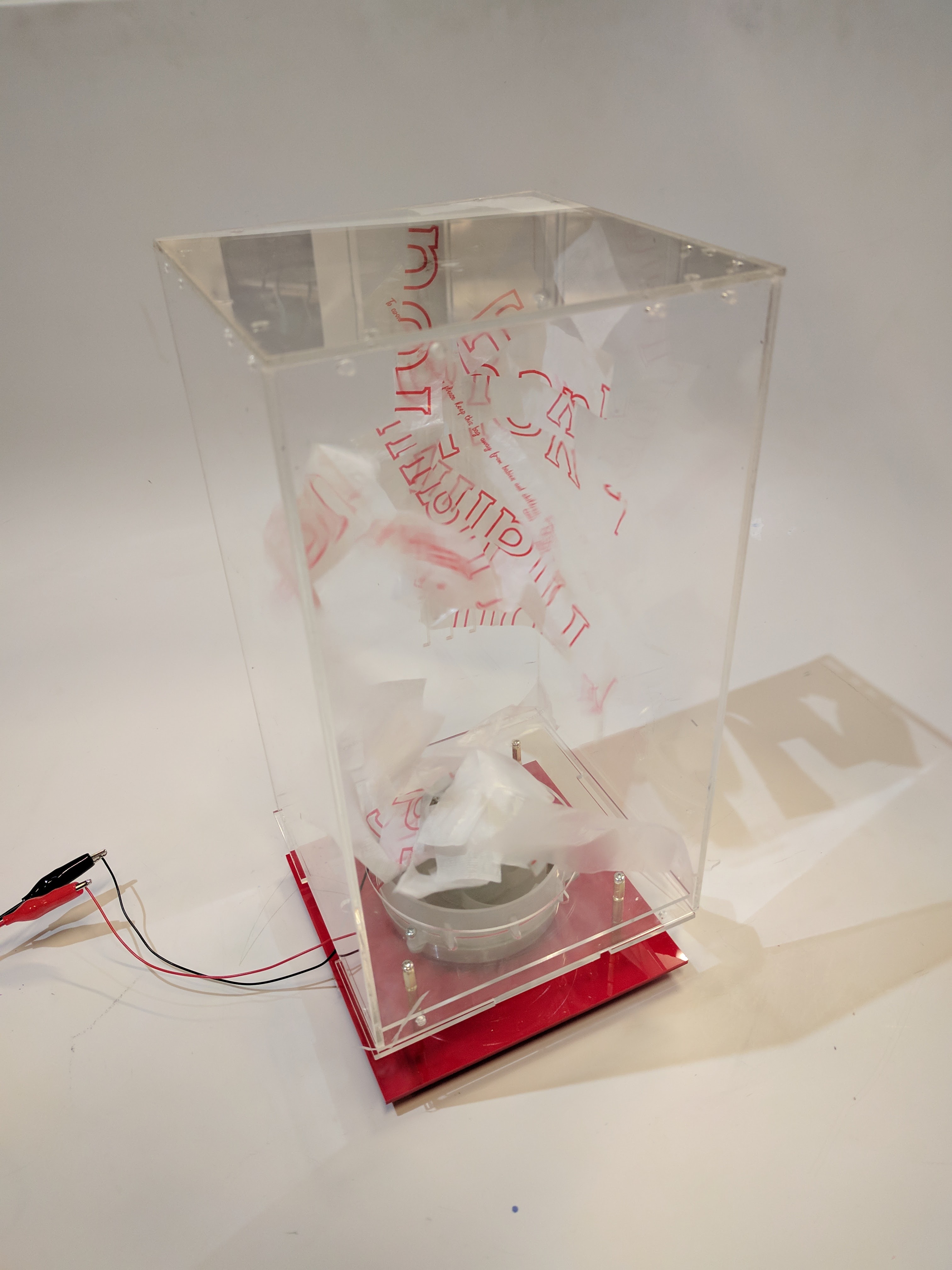
I remembered going inside of one of these money blowing boxes as a kid and trying to scoop up as much money as I could during the time frame. I wanted to create a smaller, table top version that could store my cash. When I need cash, I just need to pull a dollar through a slit.
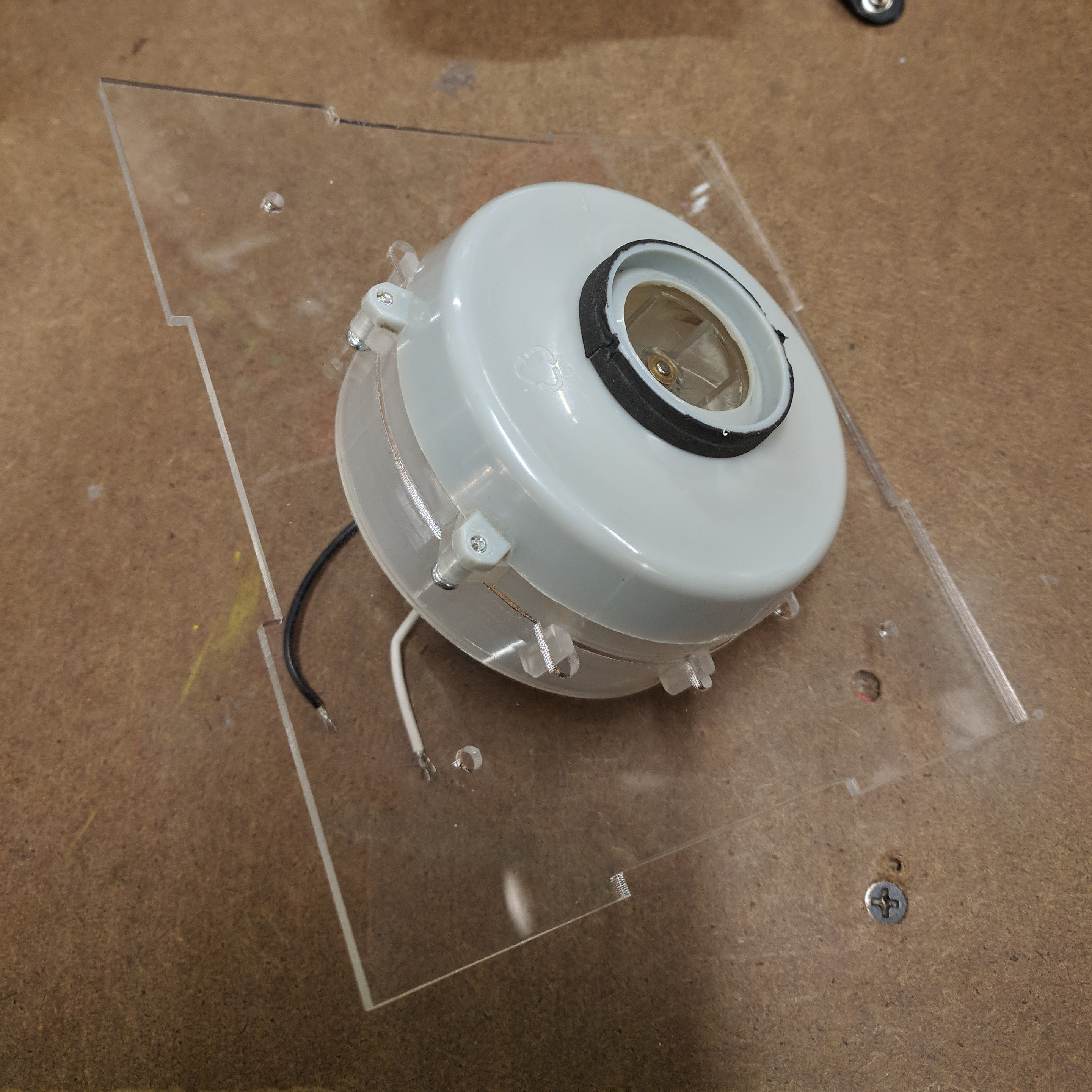
Motor
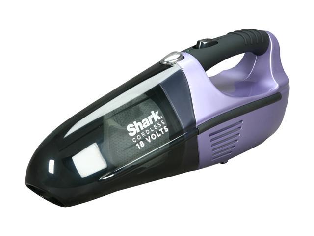
The motor was repurposed from a hand vacuum from the junk shelf. It was really hard to remove it because the screws keeping the shell together stripped. I eventually had to pry it apart.
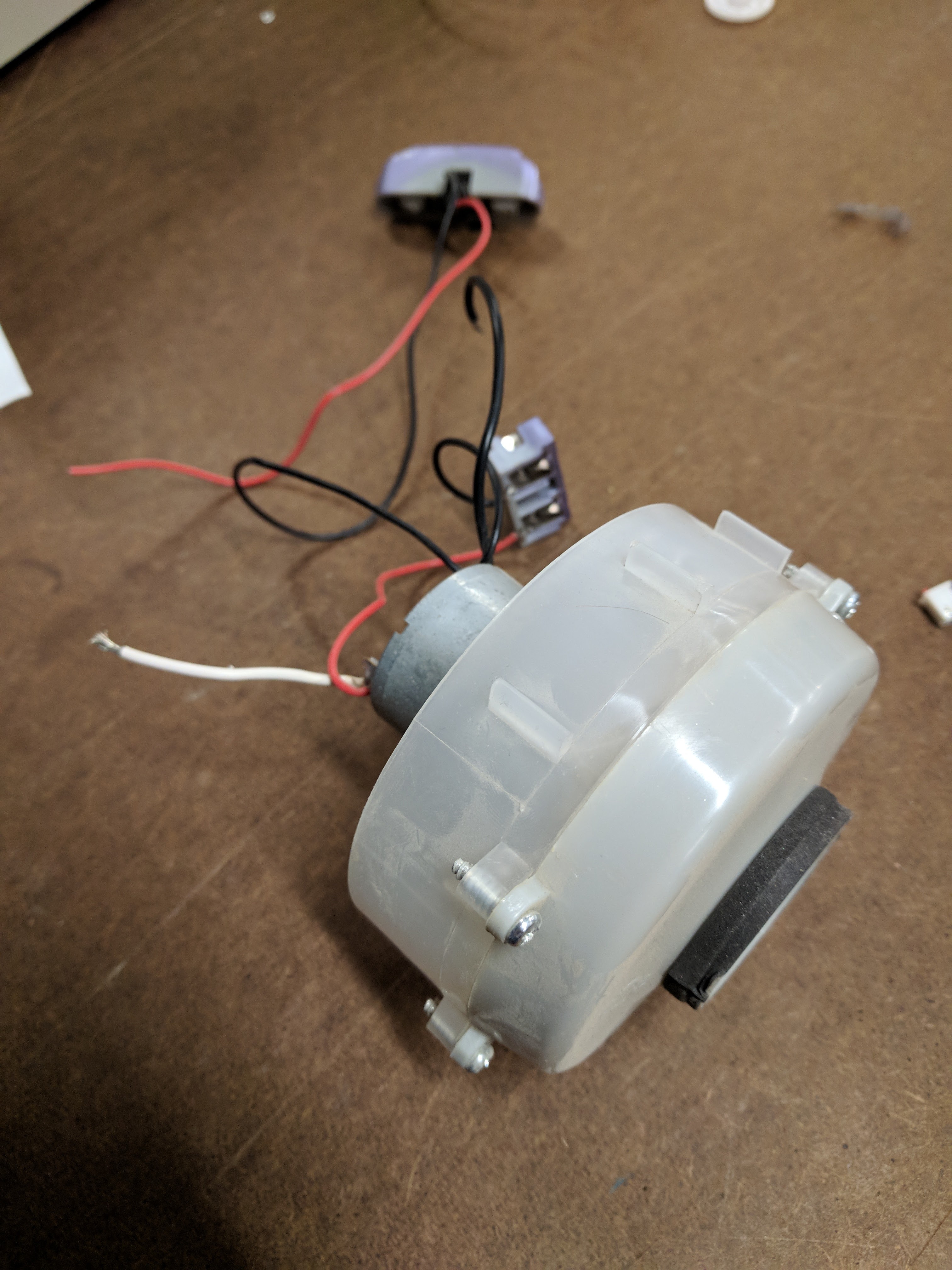 I tried to reverse the polarity of the motor so that it would blow air out rather than suck; however, reversing the leads didn’t change the direction of the air flow. I then decided to just use the ‘back’ side as the fan. So air is be drawn in through the former vacuum part (‘front’) and then blown out into the box.
Testing airflow
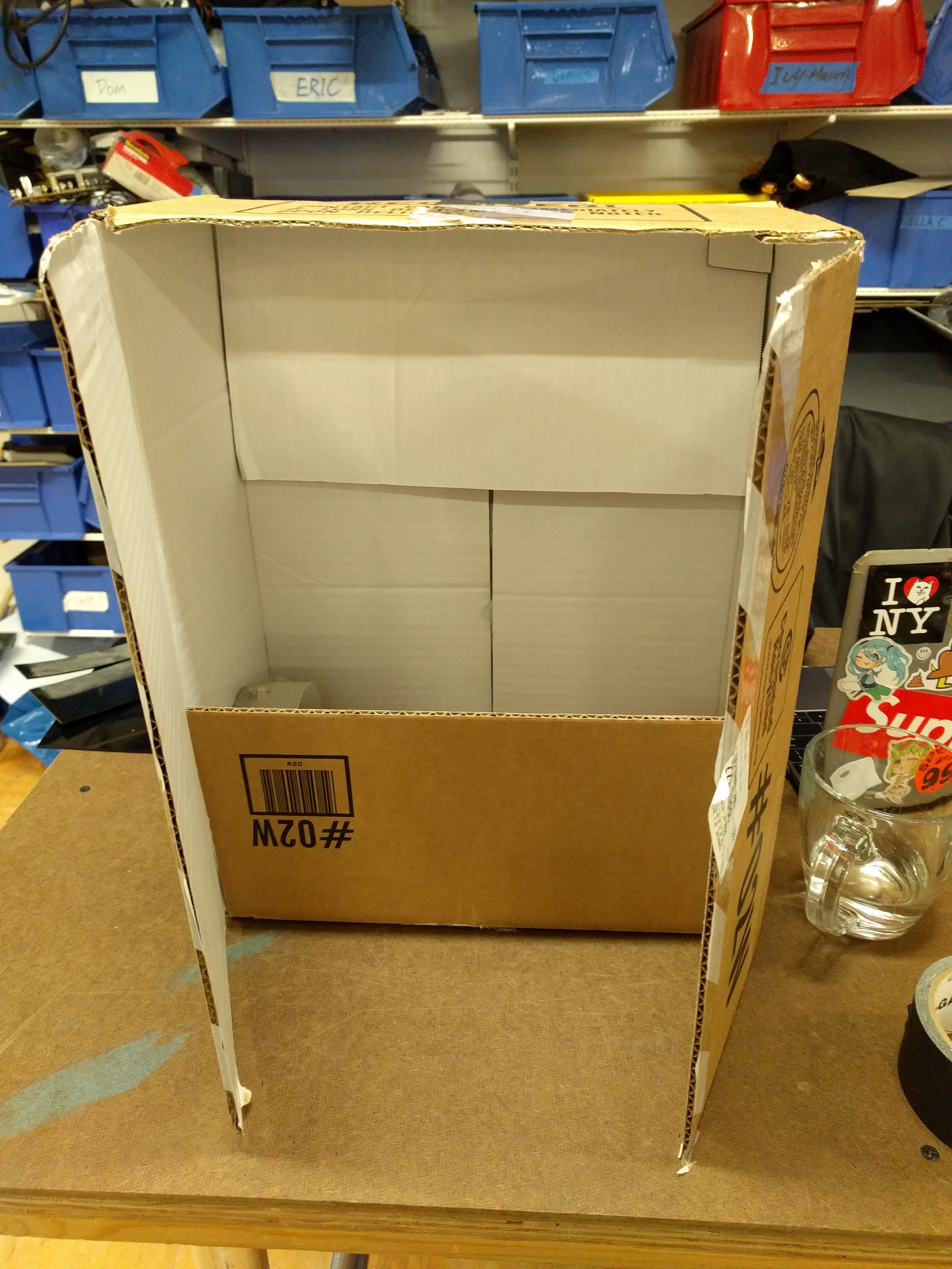
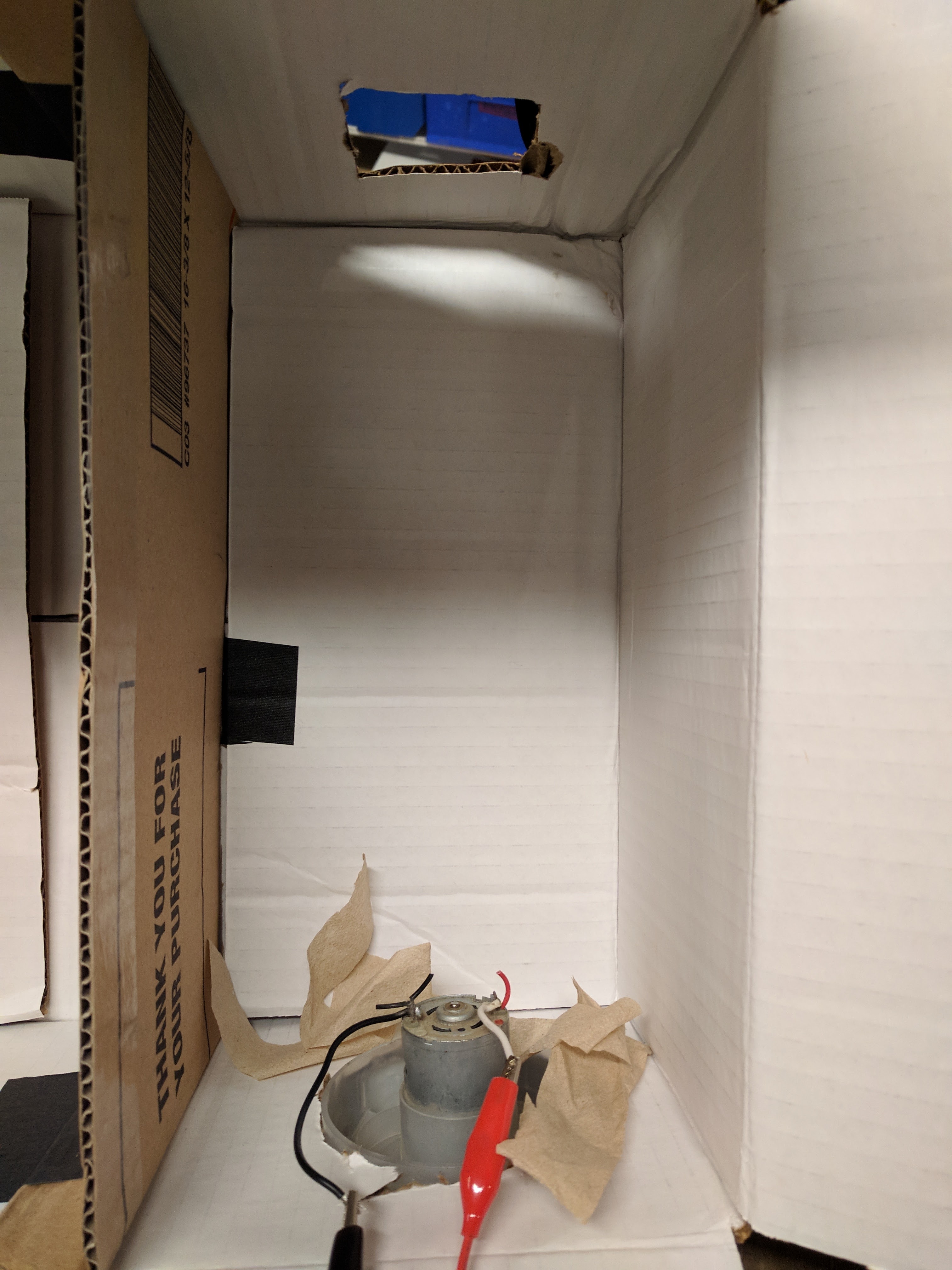
I don’t know anything about airflow so I decided to test in a cardboard box.
 I soon realized that dollar bills were too heavy to be lifted and circulated by this motor. I then used strips of paper napkins.
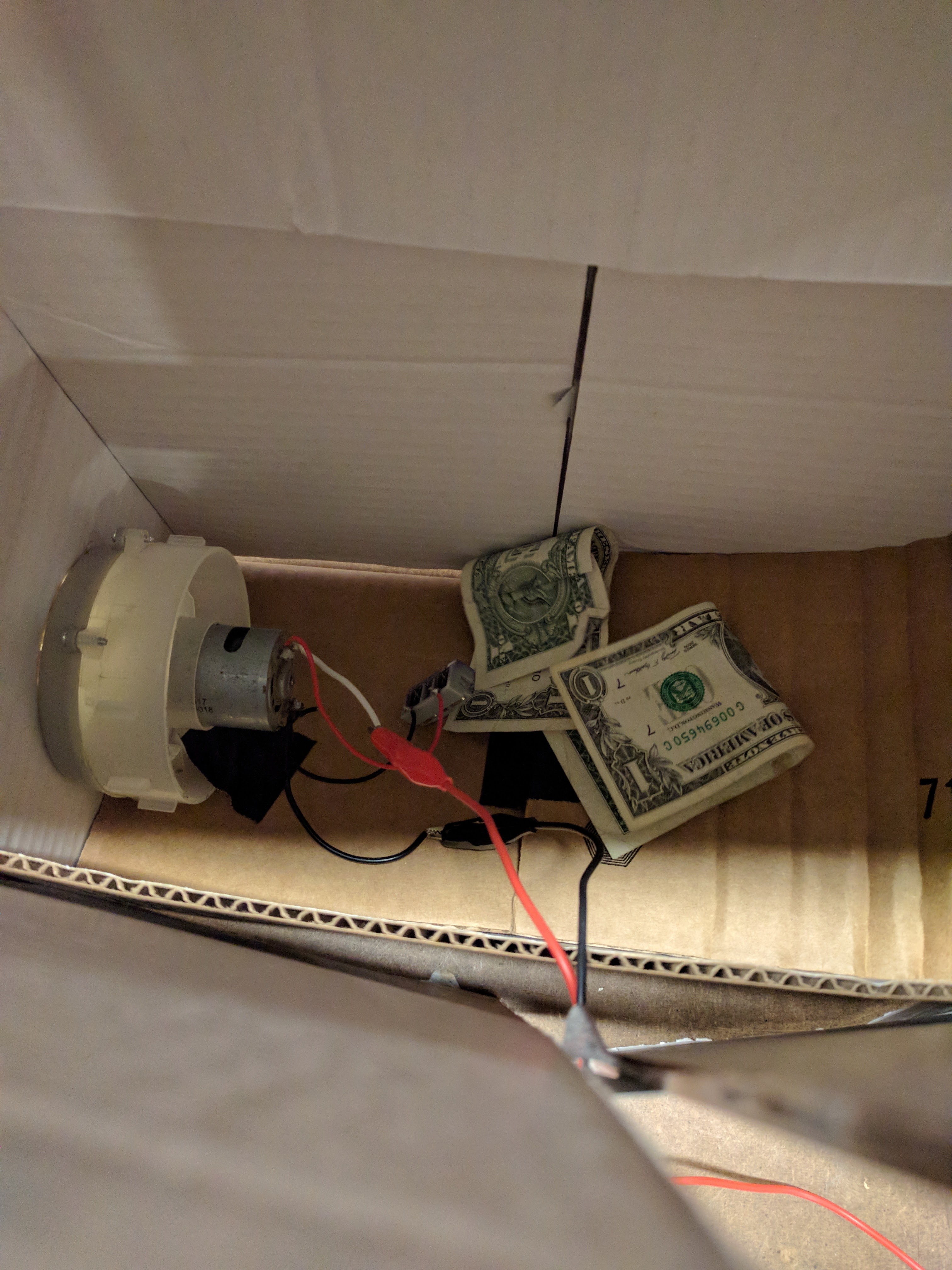 First I tested with a horizontal orientation with the fan on the side of the box. I made a curved piece of cardboard on the opposite side to redirect the air up. I learned that I needed ventilation to create an air flow.
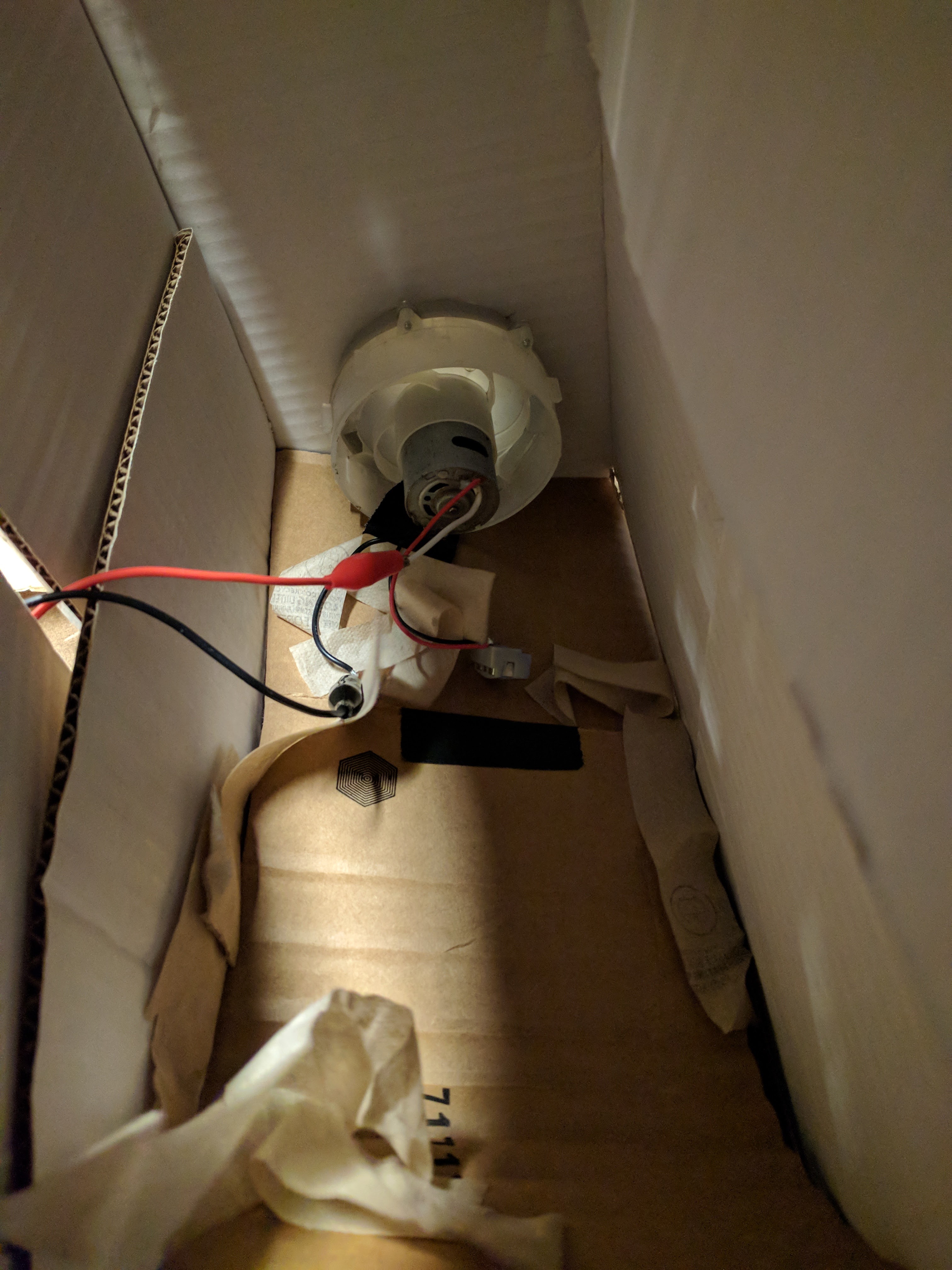 I then tried with the fan underneath, blowing up. This worked a lot better to circulate the air. However, I felt that the box was too large for the strength of the fan so I separated the box into a smaller section and tested within that.
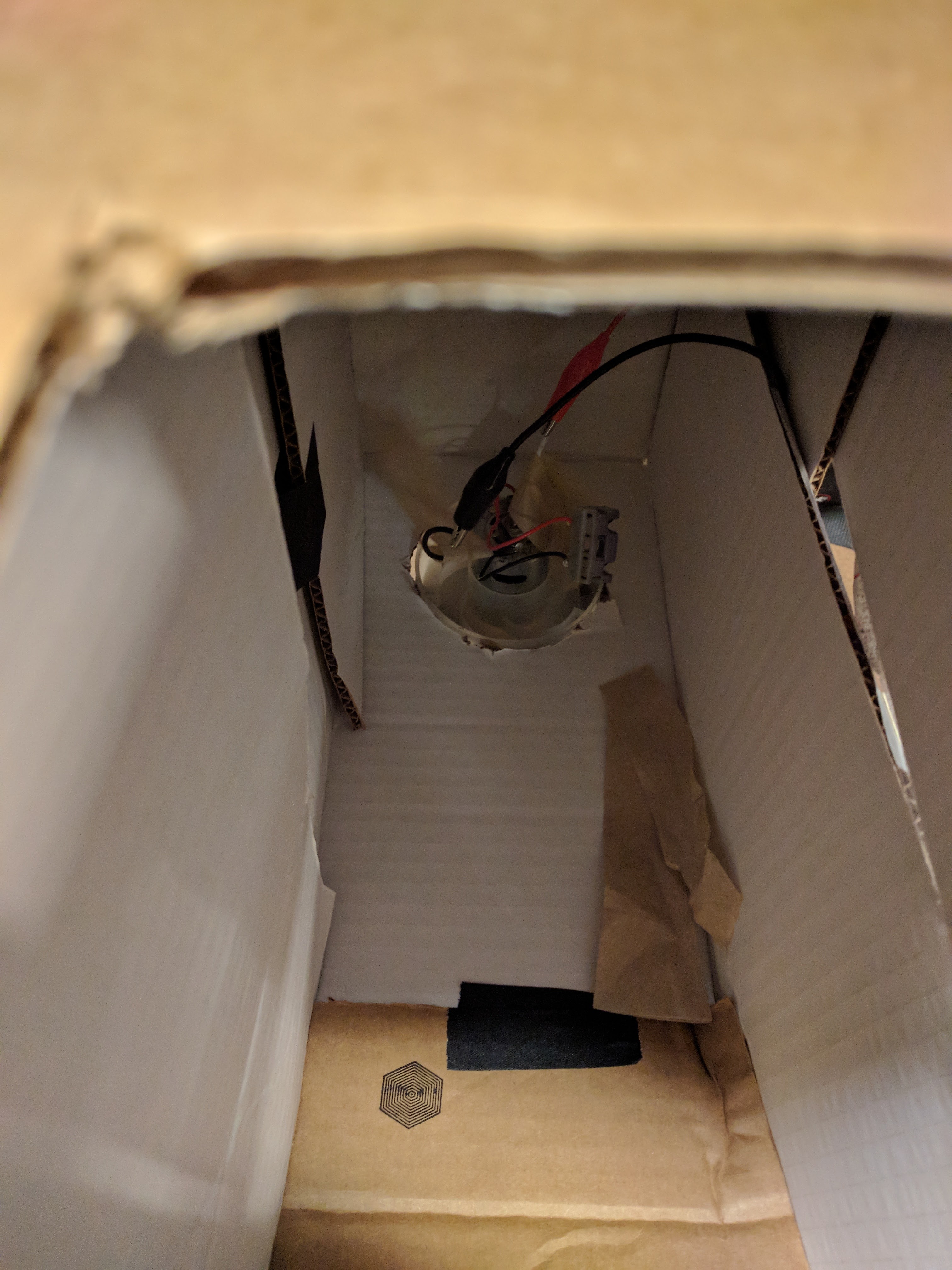
 When testing with the smaller section, I found that a side vent worked better to circulate the air than a top vent.
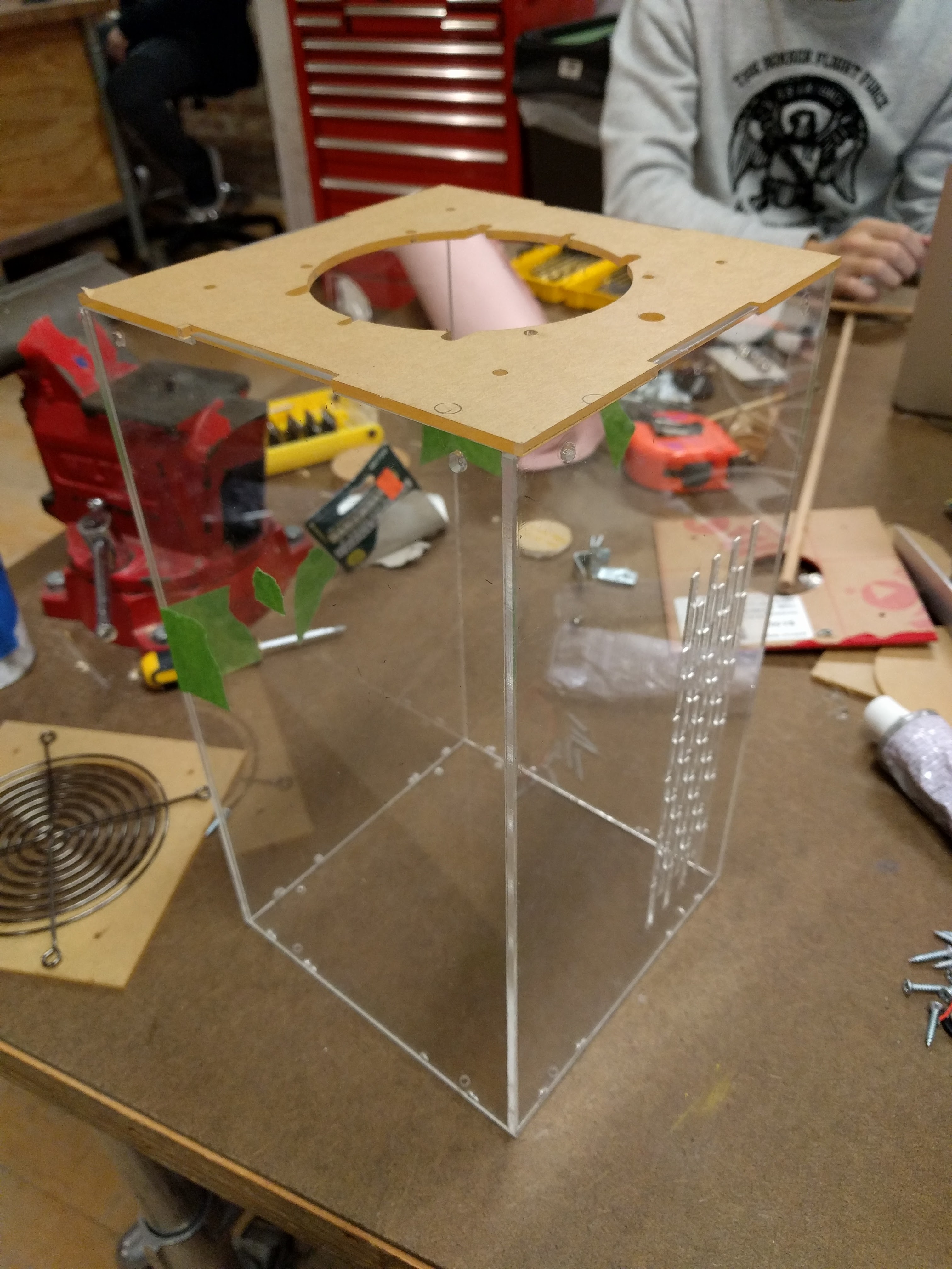
Making enclosure
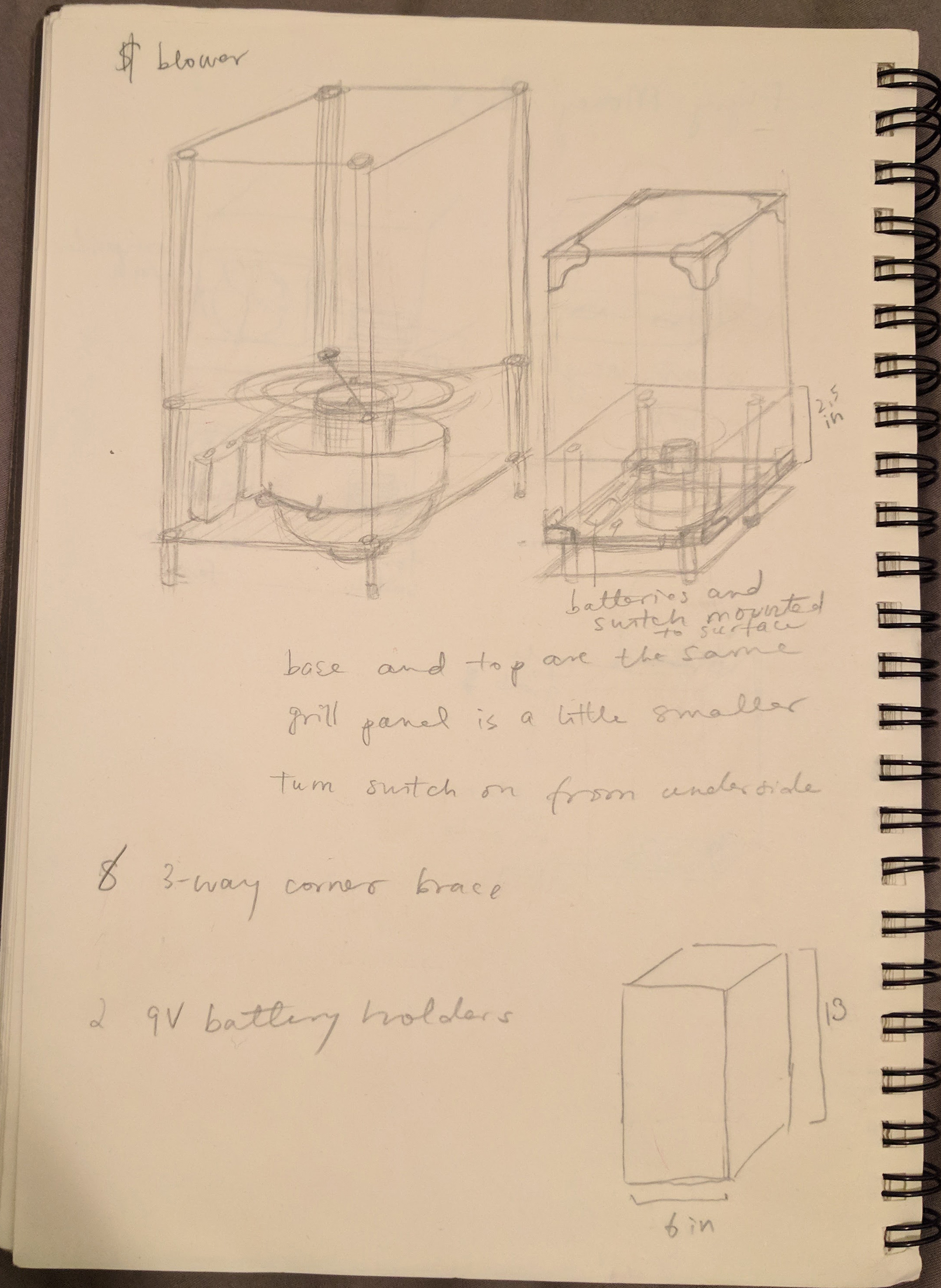
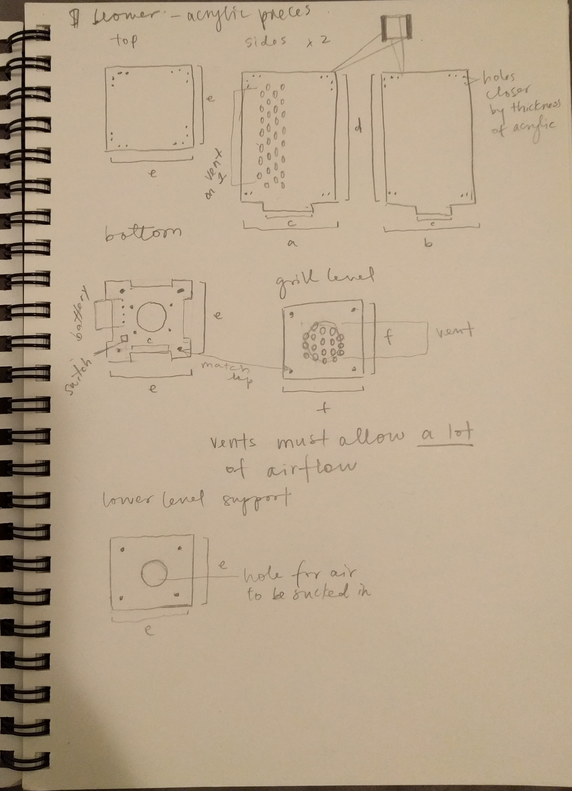
Enclosure designs that I ended up differing from. I sketched out each piece that I planned to lasercut.
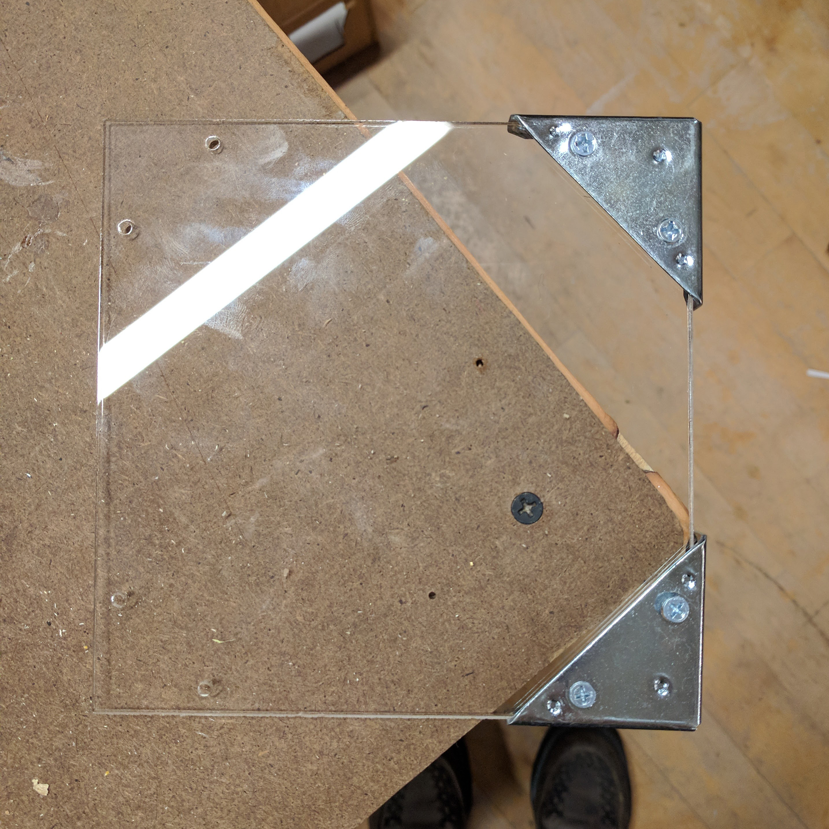
I originally planned to use metal brackets to connect the upper corners and sides. However, I messed up measuring for my lasercuts and all the holes on the right side of the panels did not measure up with the holes on the brackets. I then decided to just use acrylic solvent cement to glue the panels together in a box. This worked out really well and held together, although some angles are not exactly flush.
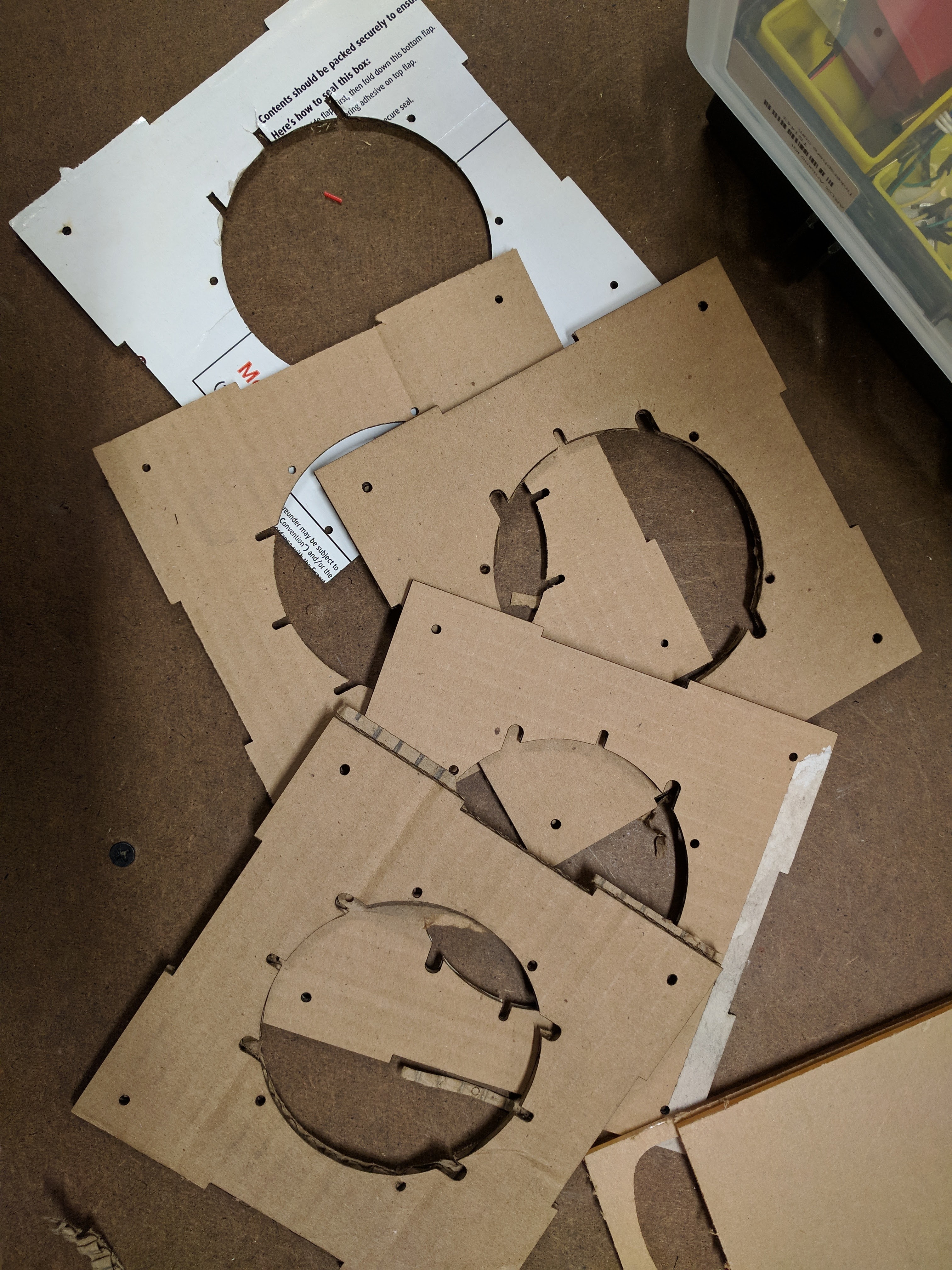
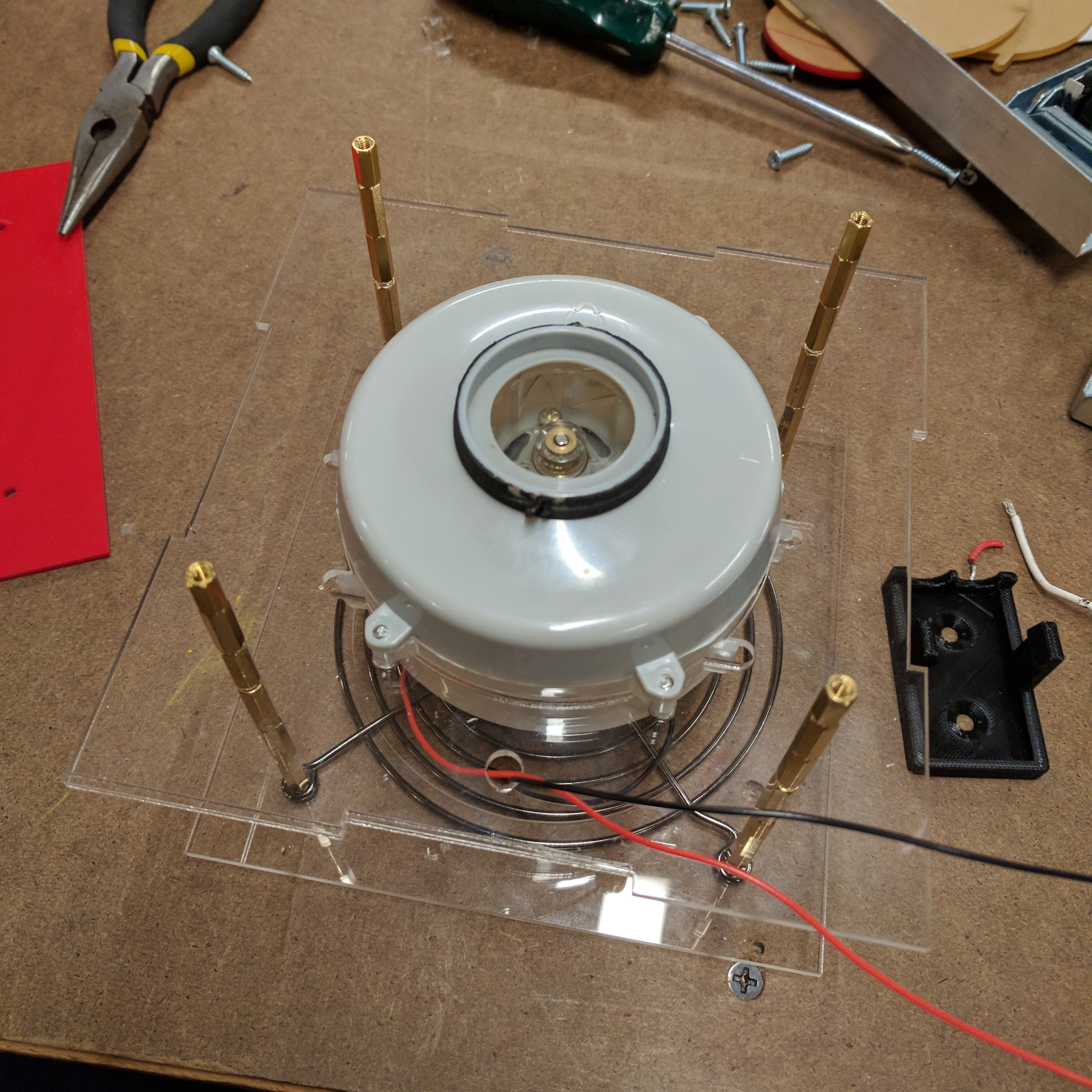
I mounted the motor by fitting a sheet of acrylic around the existing plastic fan and creating holes to match the existing screws. I used the existing screws to screw through the acrylic mount and then through the original holes in the fan. I went through many iterations in cardboard to fit the motor into the acrylic.
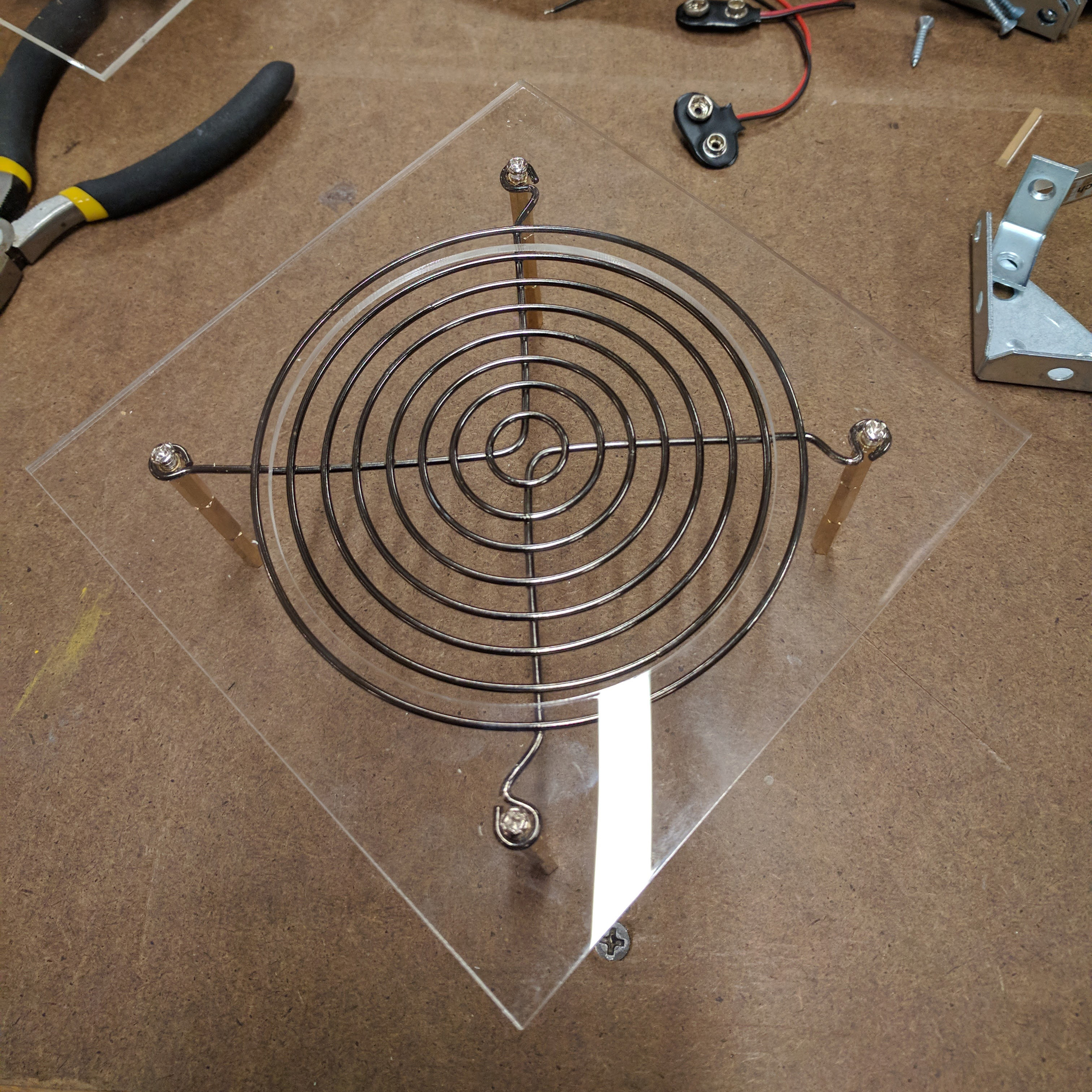
During my air flow tests, I saw that the paper often got stuck on the wires connected to the motor. That is why I designed a grill to sit on top of the motor which was mounted with standoffs. However, I didn’t end up using it because it caused even more airflow problems than the loose wires. Because of the distance between the fan and the grill, the grill layer caused a difference in air flow on either side of the layer, making the paper get sucked onto the grill. The paper flies up in a circular motion without the grill layer. I removed the metal and lowered the plastic layer to the level of the plastic fan edge.
Testing with different materials
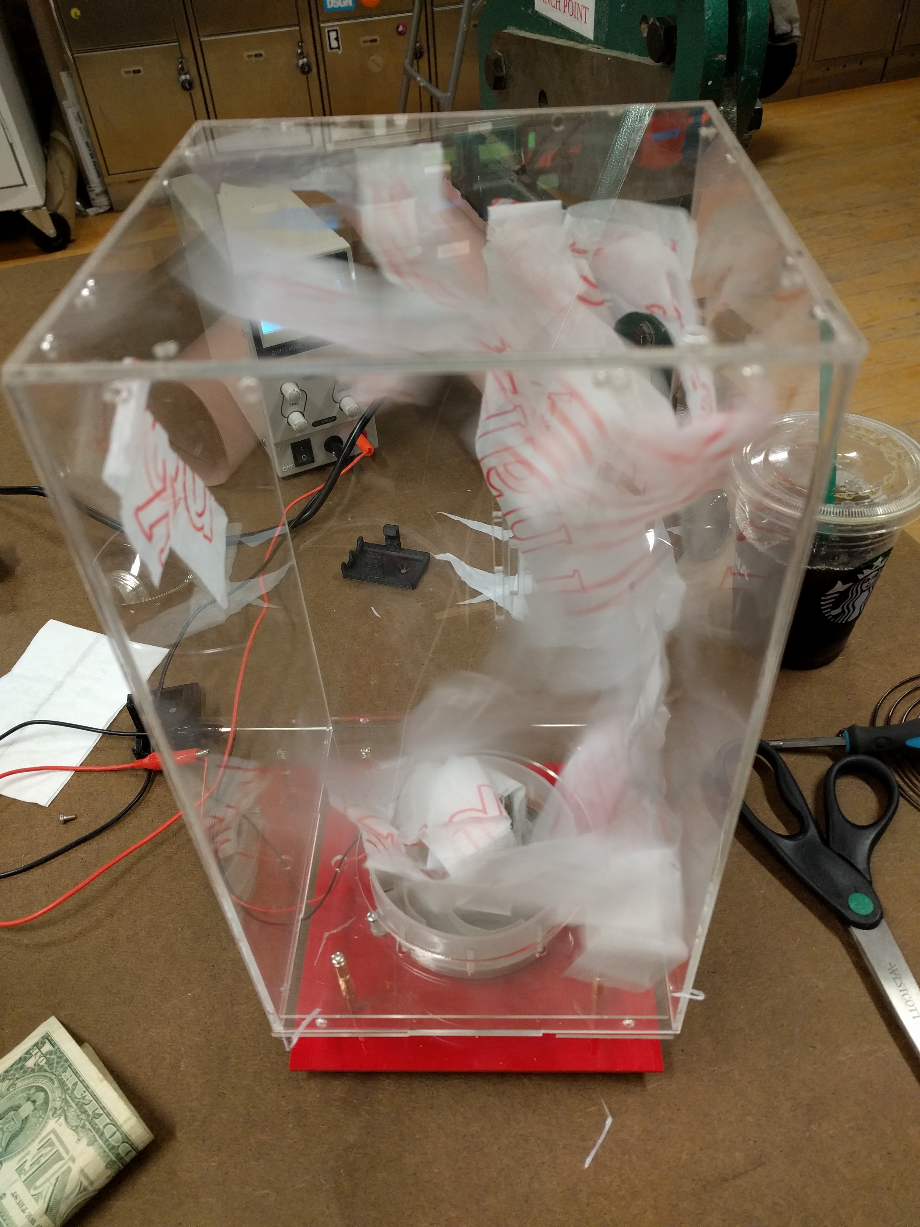 I found that the vent on the side panel was too large, making the papers stick to it. I ended up using cut up strips of trash bags and napkins. I kind of like how when the trash bag gets stuck to the side vent, you can read what’s printed on it.
Power Source
Currently, I am using a variable power supply to power the piece at 18V. Originally I planned to mount 2 9v batteries in series on the red acrylic layer. However, I realized there is no point to using batteries since the device is not portable anyway. I could mount a power supply jack to the red layer, soldering it to the loose red and black wires, and buy a 18V adapter that plugs into the wall.
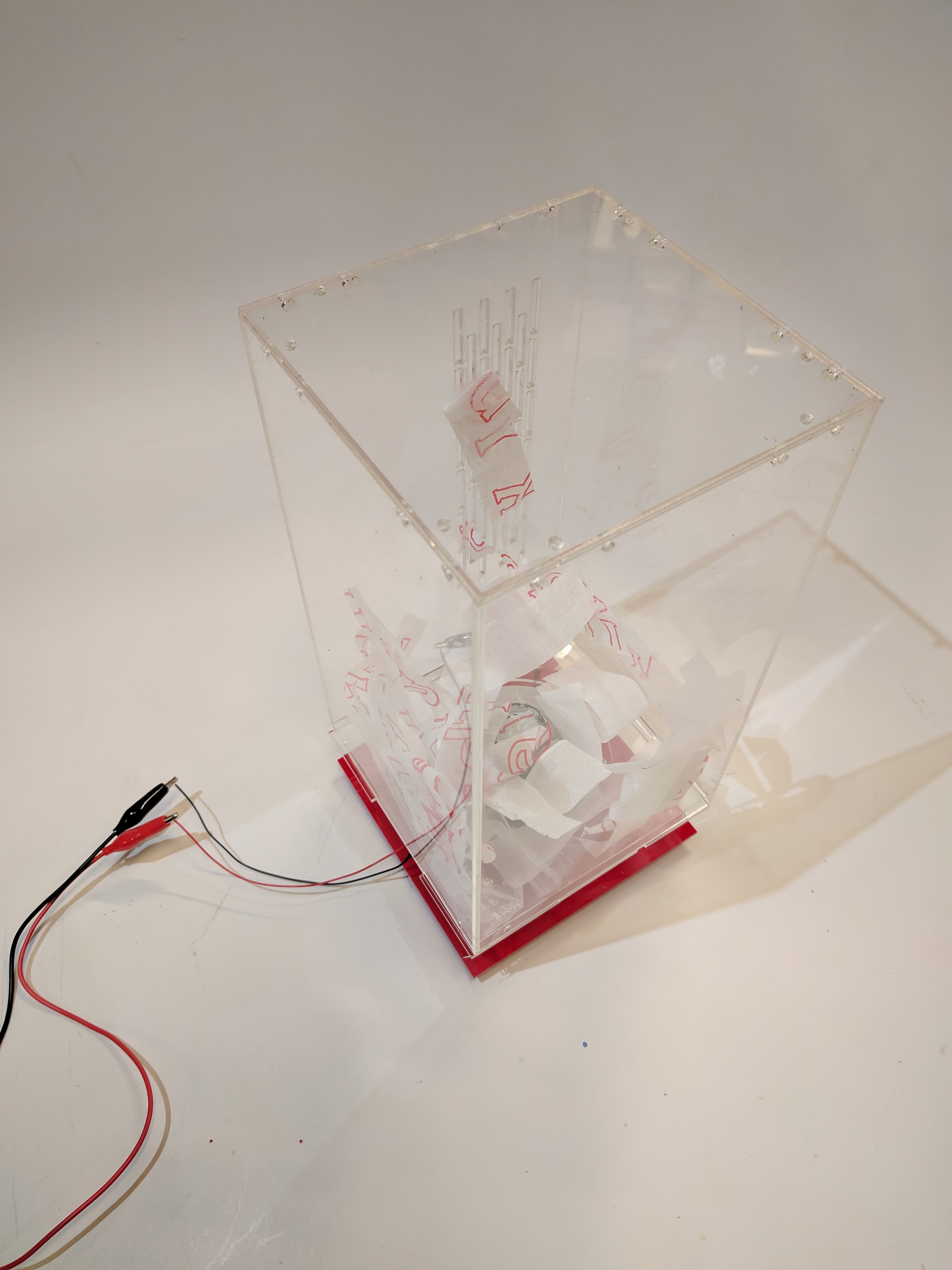
Final piece
Written on October 19, 2017
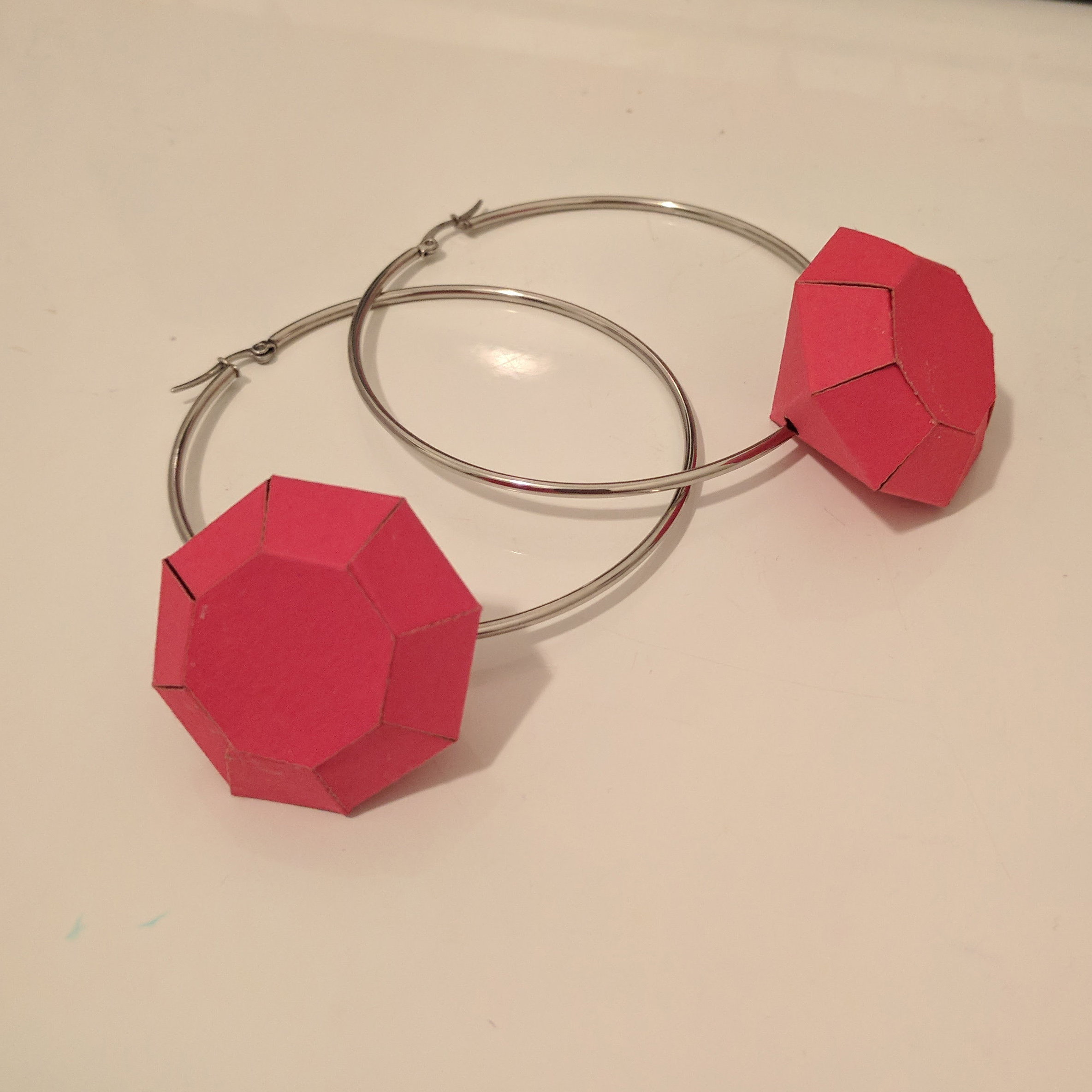
I wanted to use paper and metal wire to create a design inspired by a diamond ring. I used paper for the gem stone part and metal as the holder/jewelry part. Figuring out the process and design took me a long time and many tries. Basically, I learned that I hate working with paper and I’m really bad at soldering.
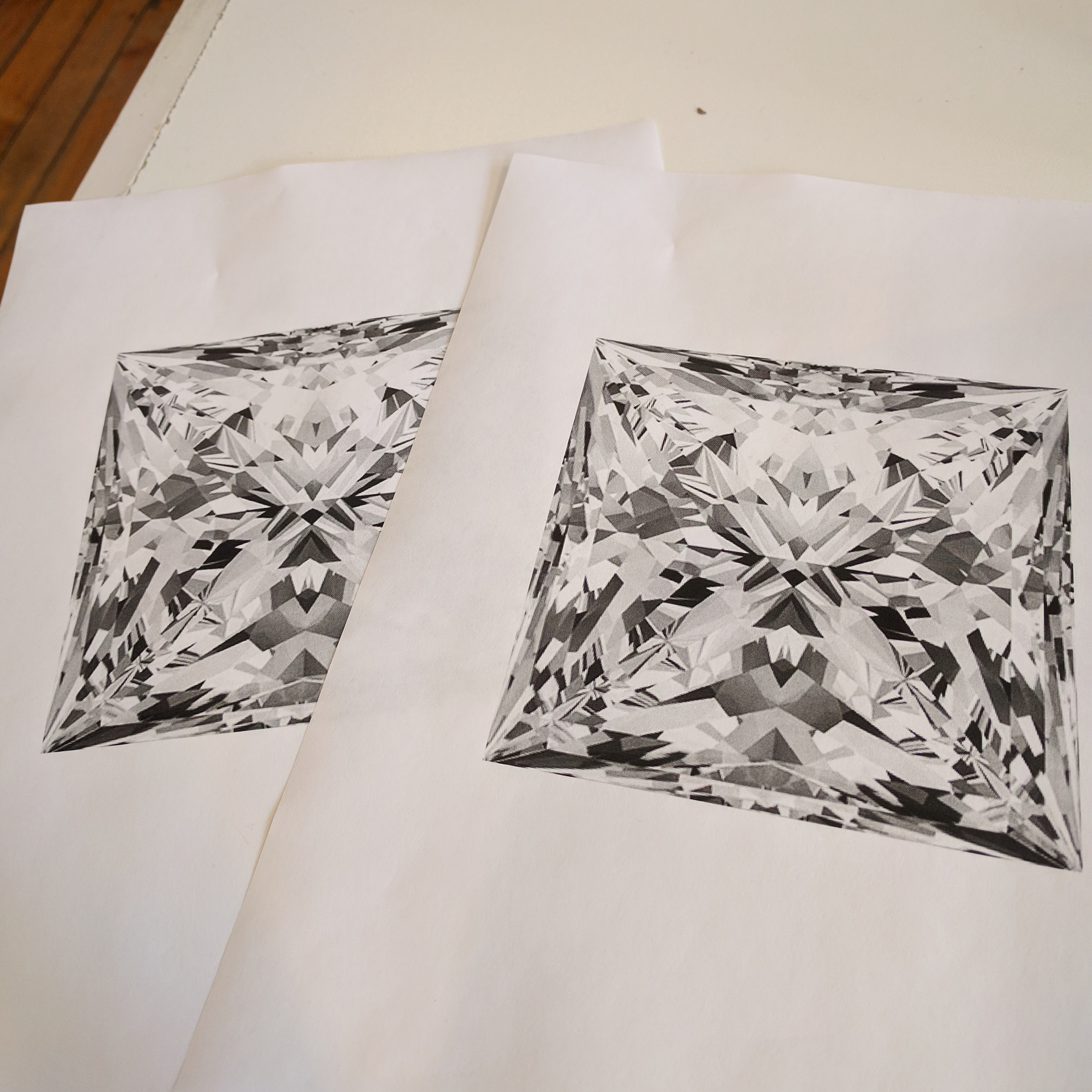
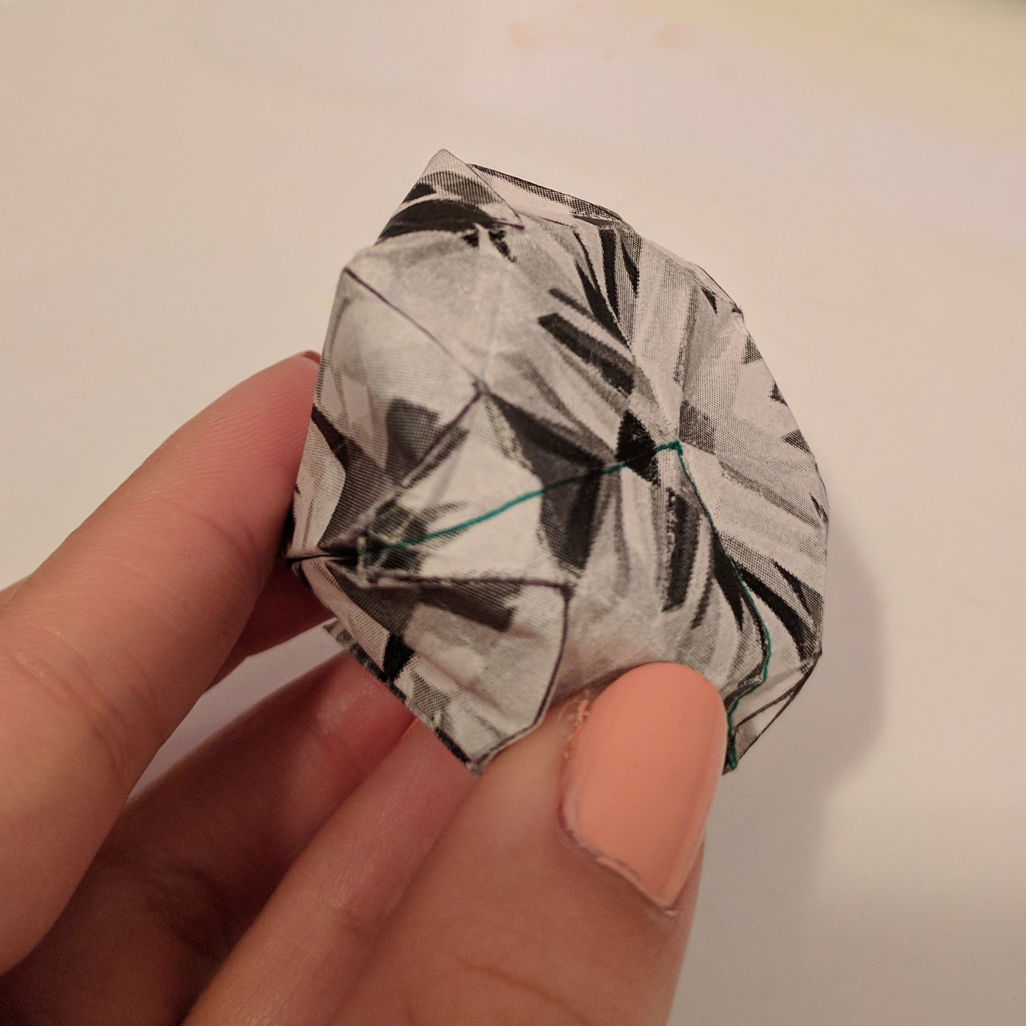
Originally, I thought that I could construct a paper diamond using origami. I printed out a diamond design onto paper and cut it into a square.
I then followed this really complex origami tutorial. The result was not what I wanted. I didn’t think it was worth practicing further since I didn’t think I would get skilled enough to make it at an even smaller size.
I decided to go simpler and glue tabs together. I downloaded a pattern from this blog and traced the outline on Illustrator to laser cut. I first tried with regular computer paper. I glued the edges with Elmer’s Multi Purpose Glue-All. I attempted to make a ring out of soldering wire and attached it through the bottom point of the diamond.
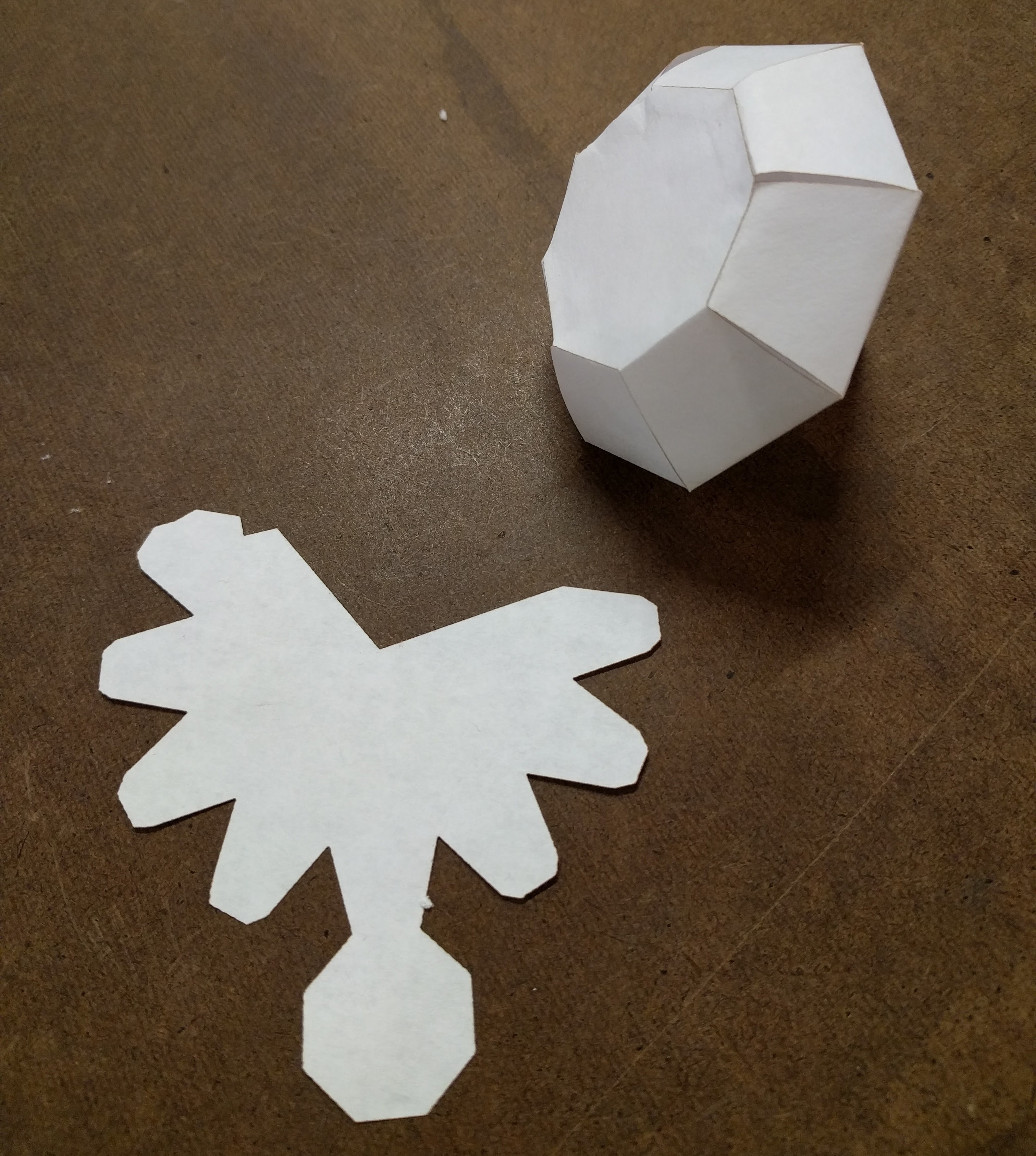
From this, I learned that computer paper was way too thin, soldering wire was too soft, and the size of the diamond was too large.
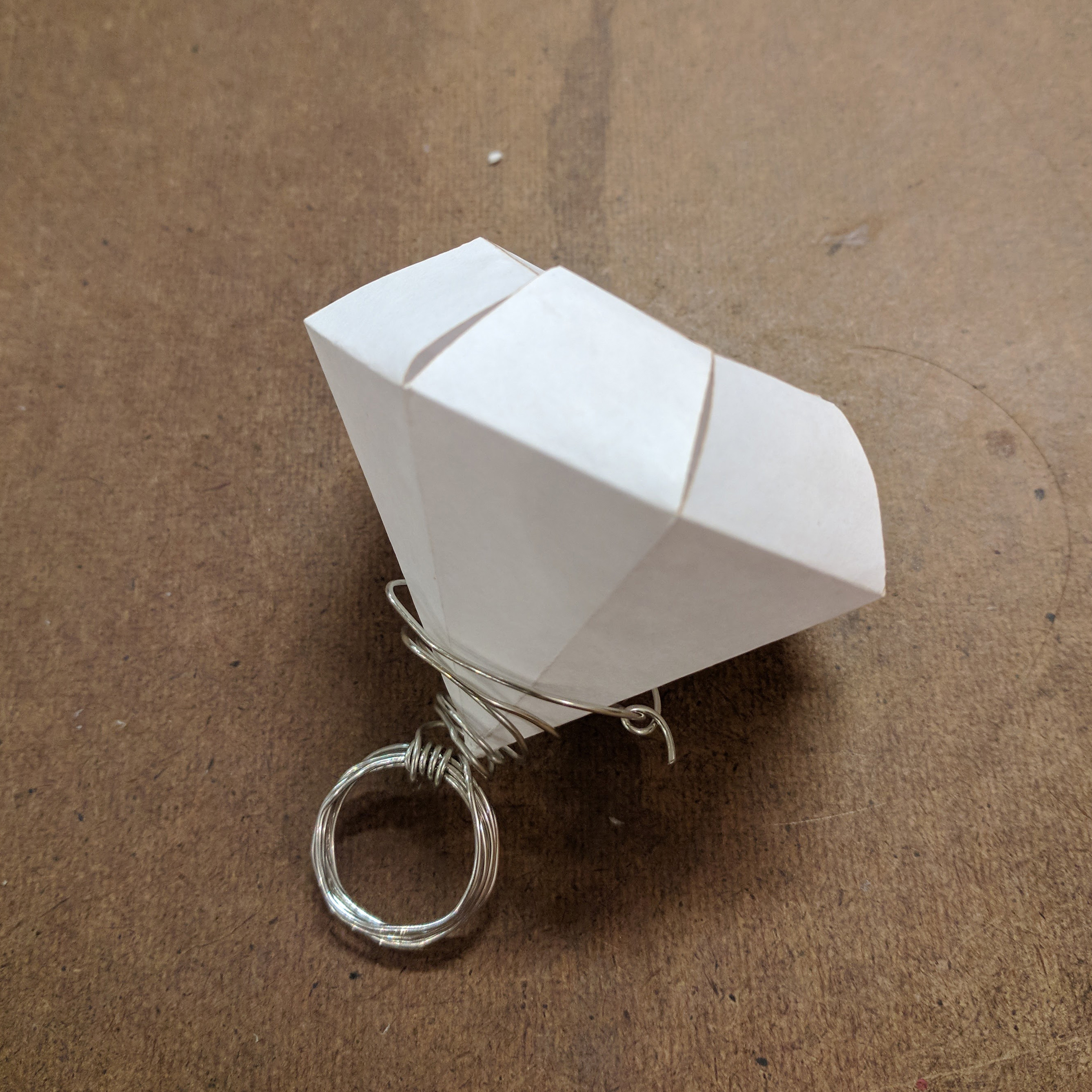
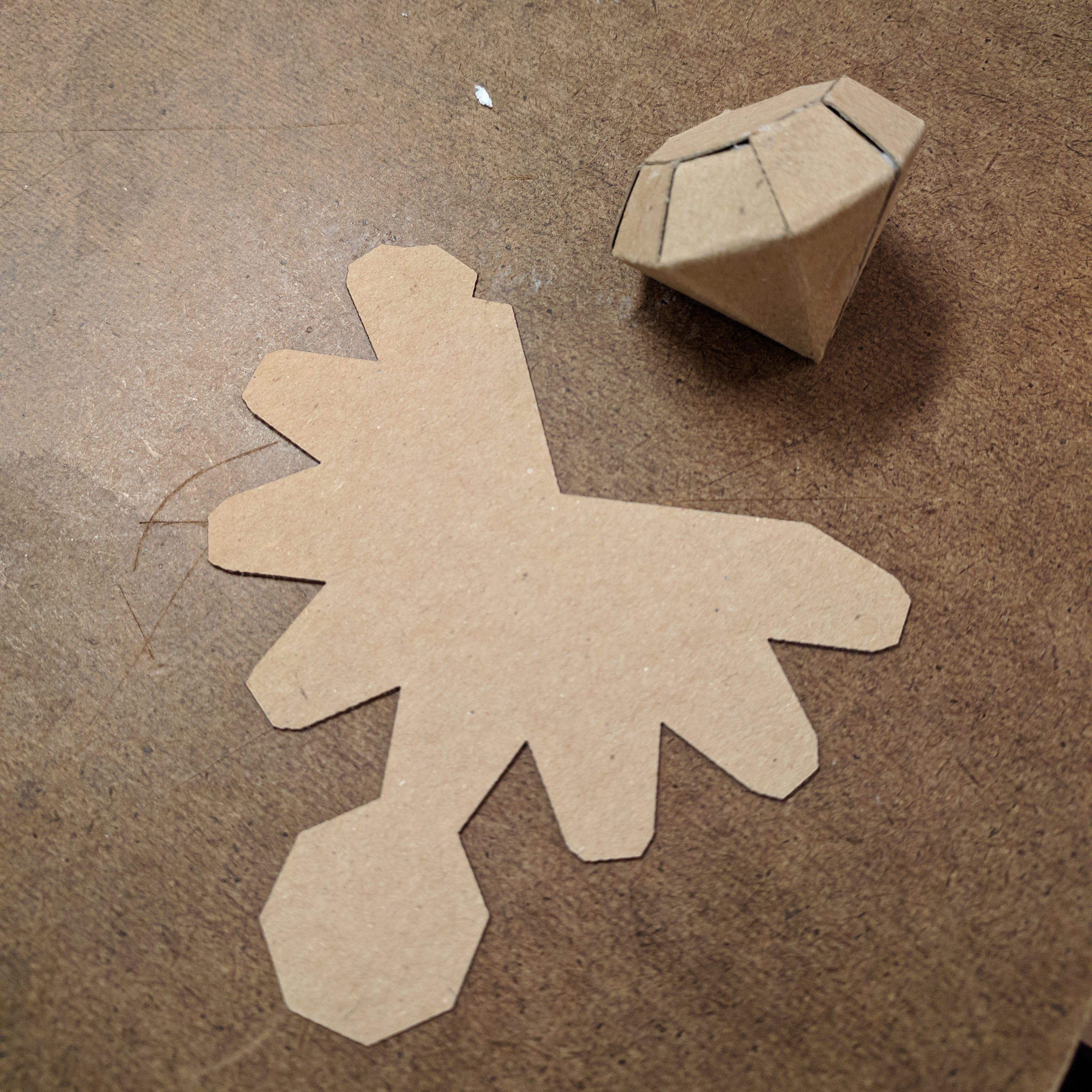
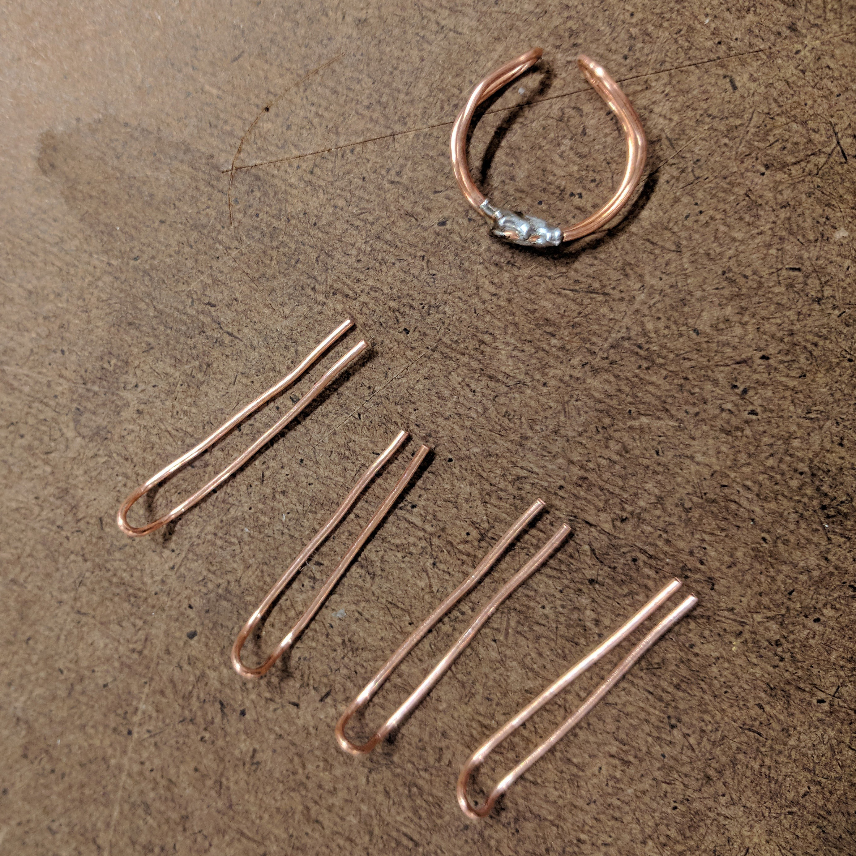
I then tried lasercutting the pattern out of a thin cardboard/mat board. This glued together really well. I tried making the ring portion out of copper wire with holders that gripped the top edges of the diamond (like a real diamond ring). Soldering this together with solder failed miserably. I couldn’t get the top holder sections, once connected, to fuse to the ring portion.
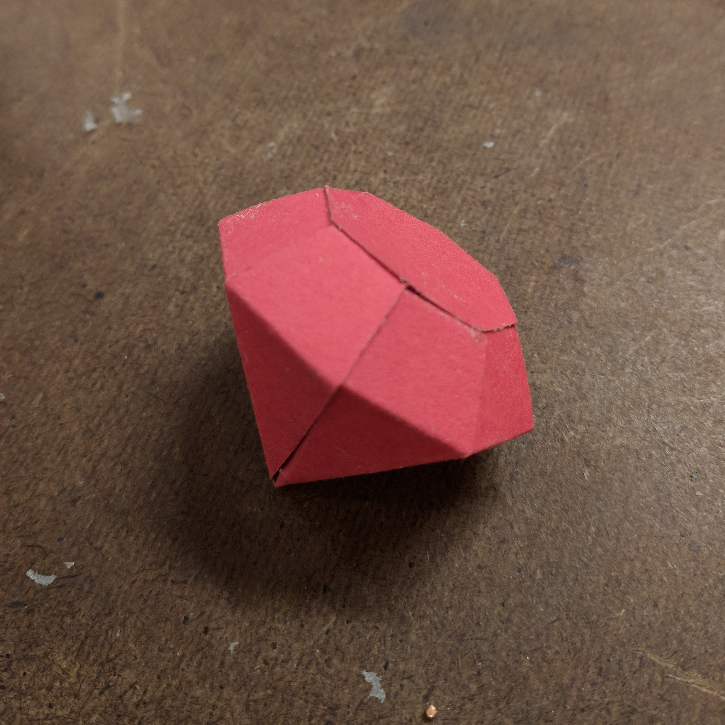
I then thought that I could just string the paper portion into hoop earrings. It would have the look of a jeweled ring but actually be slightly more functioning jewelry. I wanted to try using thick red paper I found. This held together well with the glue.
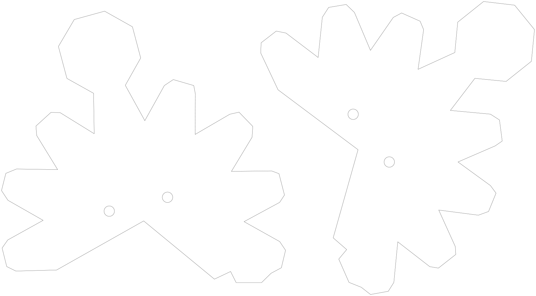
I added large holes to my laser cut pattern. I then tried assembling my prototypes.
Final lasercut pattern:
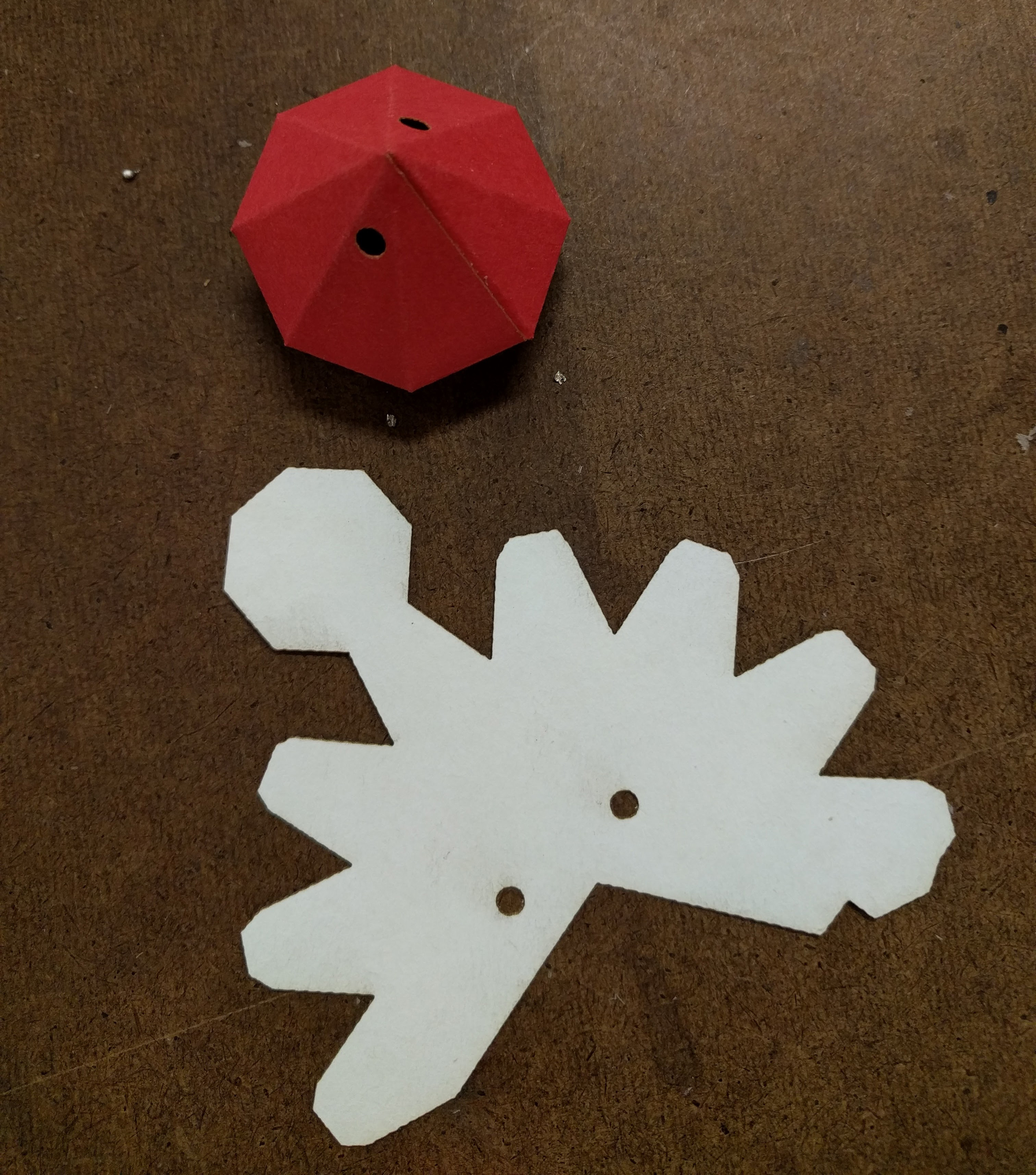

Final images with the hoop earrings attached:
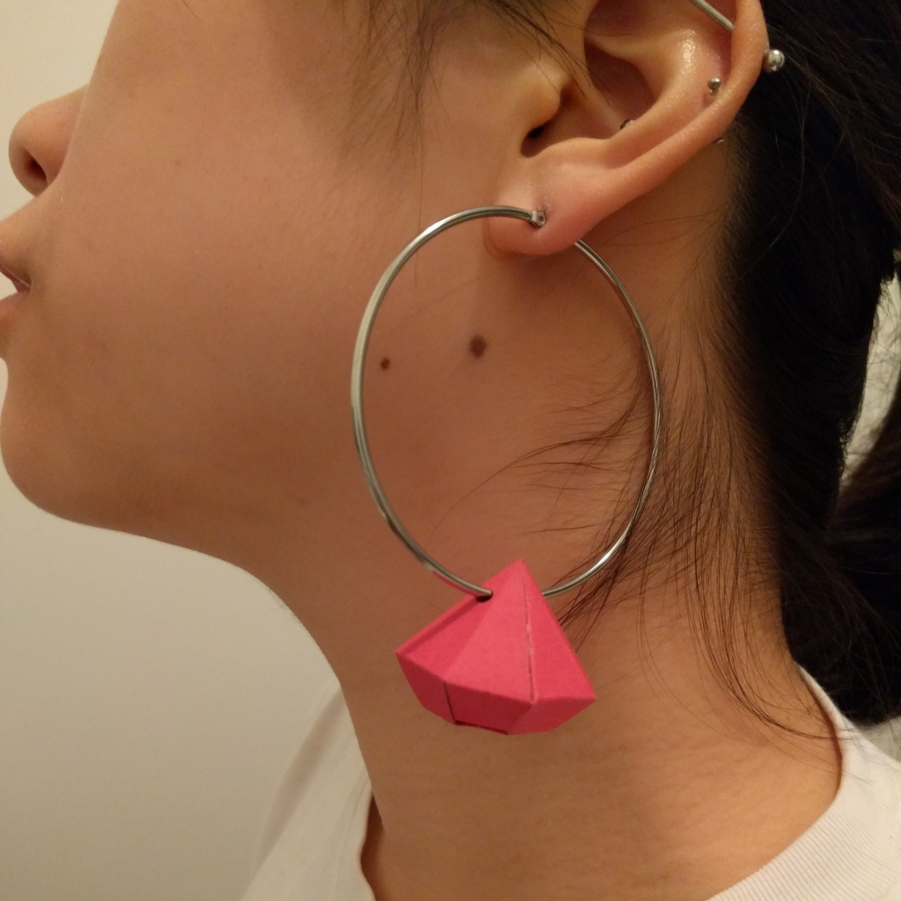
It looks okay. I would improve the design by using reflective/metallic paper, making even smaller paper diamonds, using smaller proportional hoop earrings, and figuring out a sealant that would preserve the fragile paper.
Note: I didn’t have time to fix the comments section on my blog this week. I’ll try to figure it out for next week.
Written on October 11, 2017
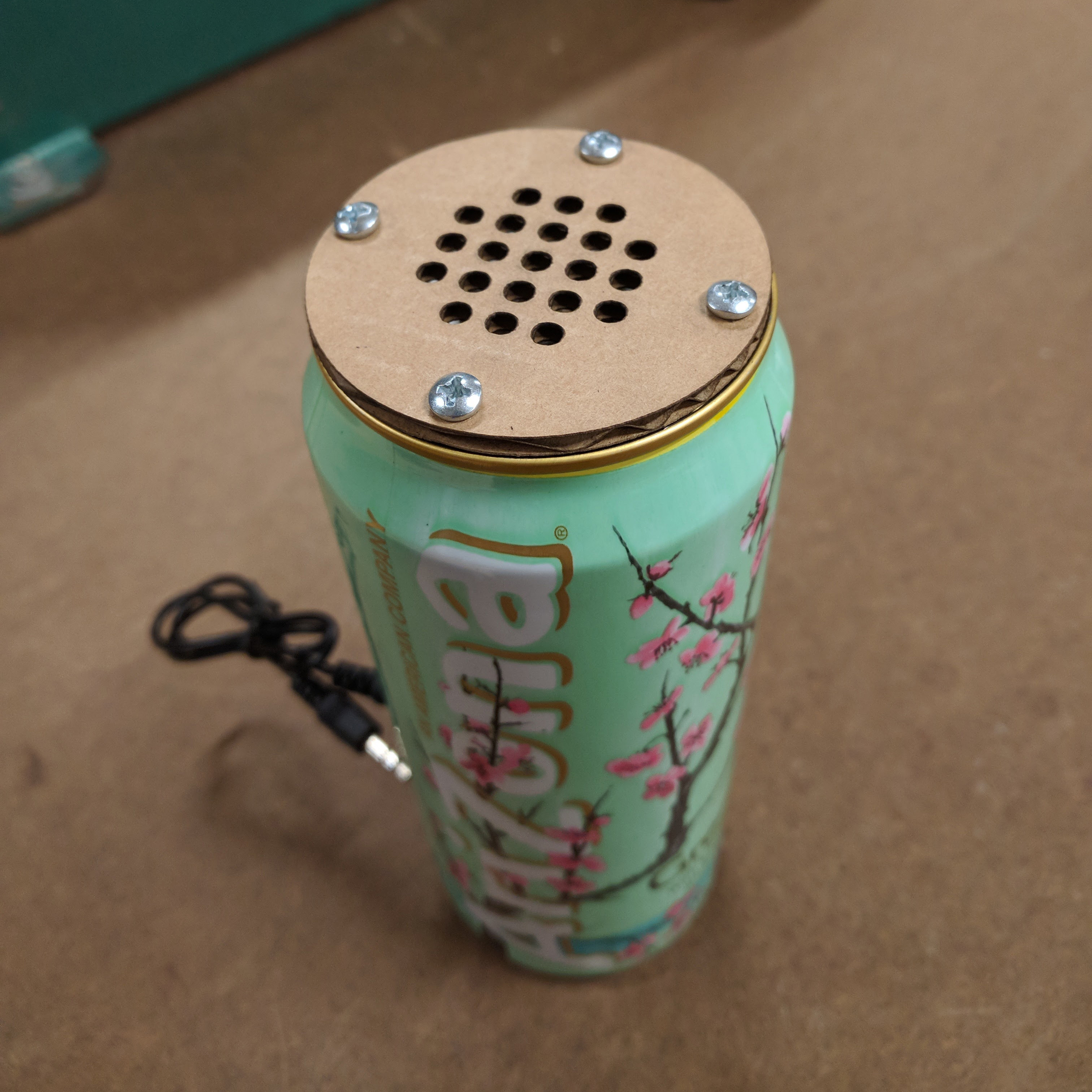 I made an Arizona can into a speaker. I wanted to be able to hold the can like I would normally hold an Arizona while also playing music on it! Since this assignment focused on enclosures (and not whatever’s inside), I took apart a cheap store bought rechargable bluetooth speaker and used its components.
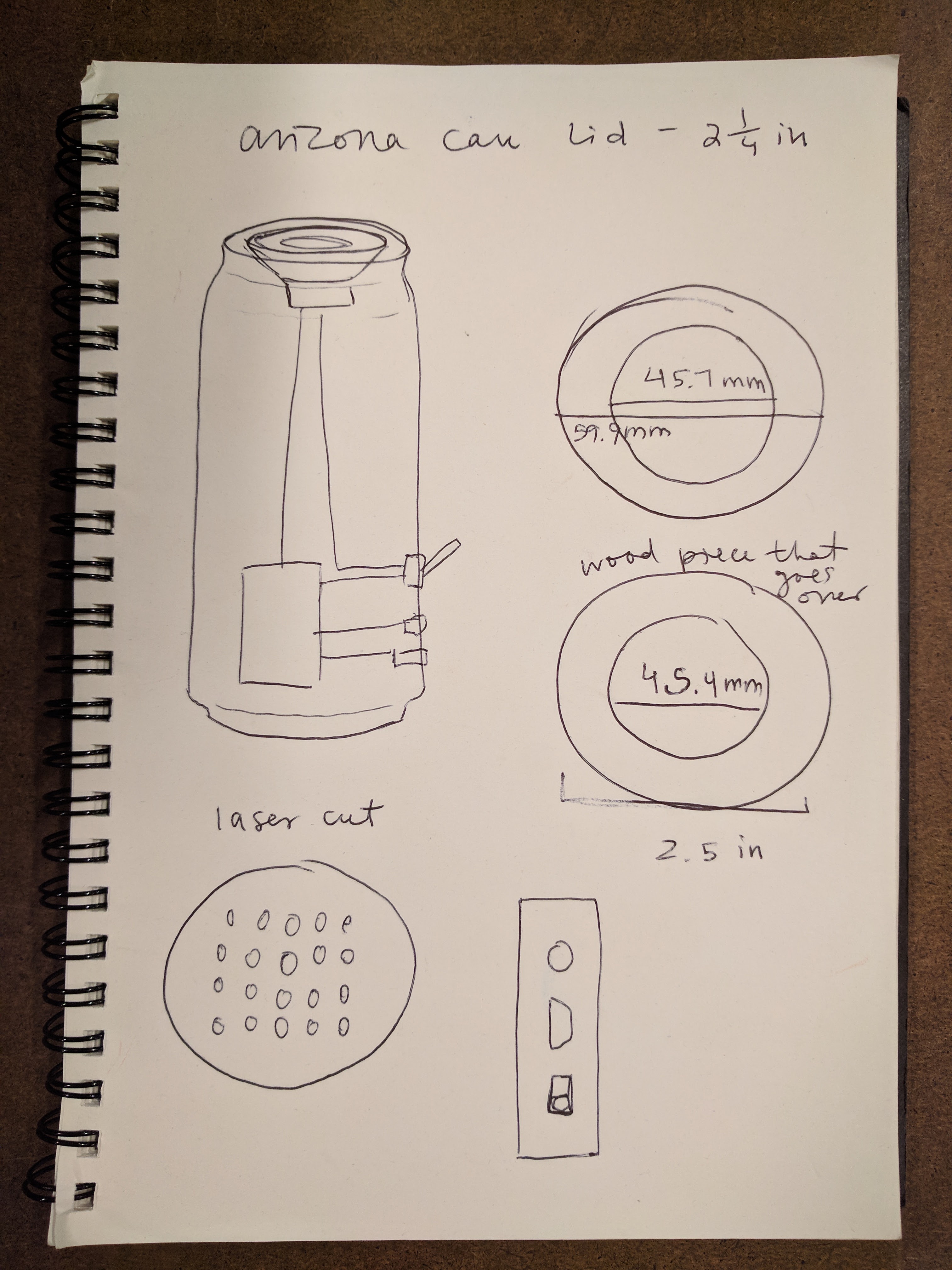
I planned on cutting a hole at the top of the can where the speaker would point out. This hole had to be smaller than the speaker, creating a rim where the edge of the speaker could rest ontop. Then, I would lasercut a surface to go on top and secure it with screws going down into the top of the can.
Rough sketches:
My materials were an empty Arizona can that I drank the night before and an $8 speaker.

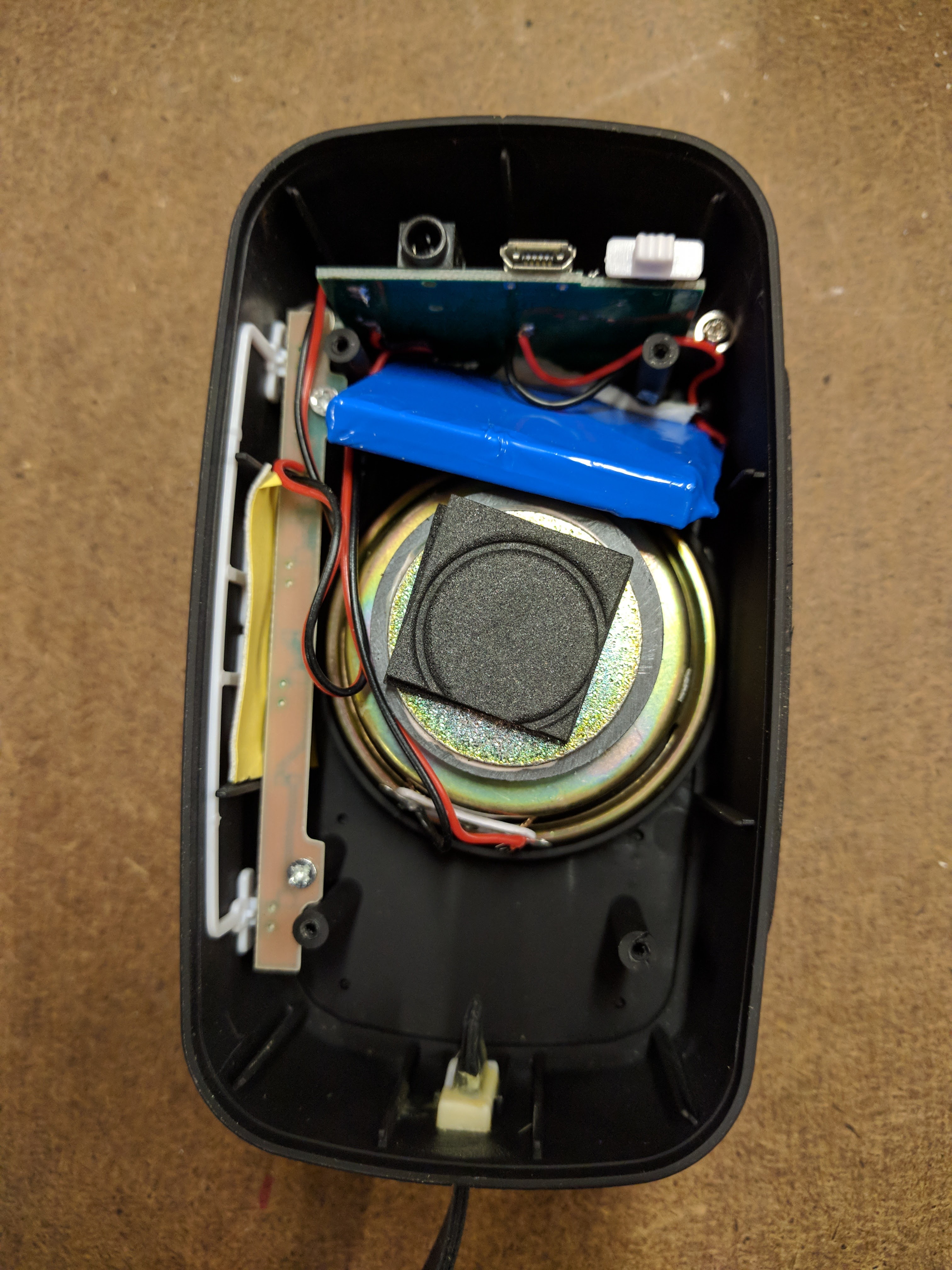
I began by taking apart the original speaker and unscrewing the circuit boards from the enclosure.
I then began cutting out the top hole where all my components would enter the can and the speaker would point out of. I used a nibbler to roughly cut it out while constantly fitting it against the speaker. I then sanded down the edges.

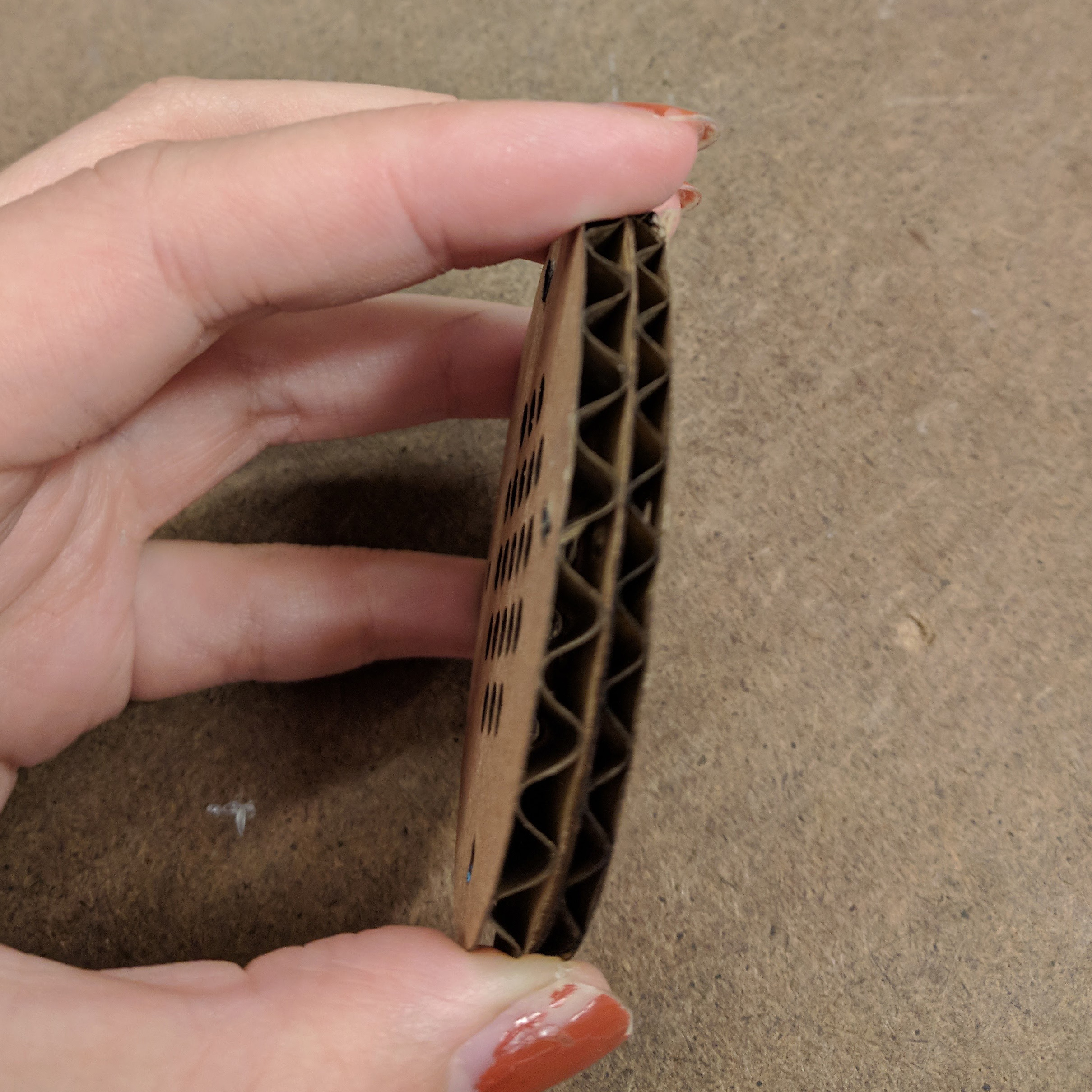
I designed the pieces that had to be lazer cut: the grill surface that would be installed on top of the speaker and the surface the ports would fit into. I used digital calipers to measure the diameter of the can top as well as the distances and sizes of the port holes. I was originally going to use a thin wood board; however after practicing on cardboard, I decided I liked the look of cardboard with the can.
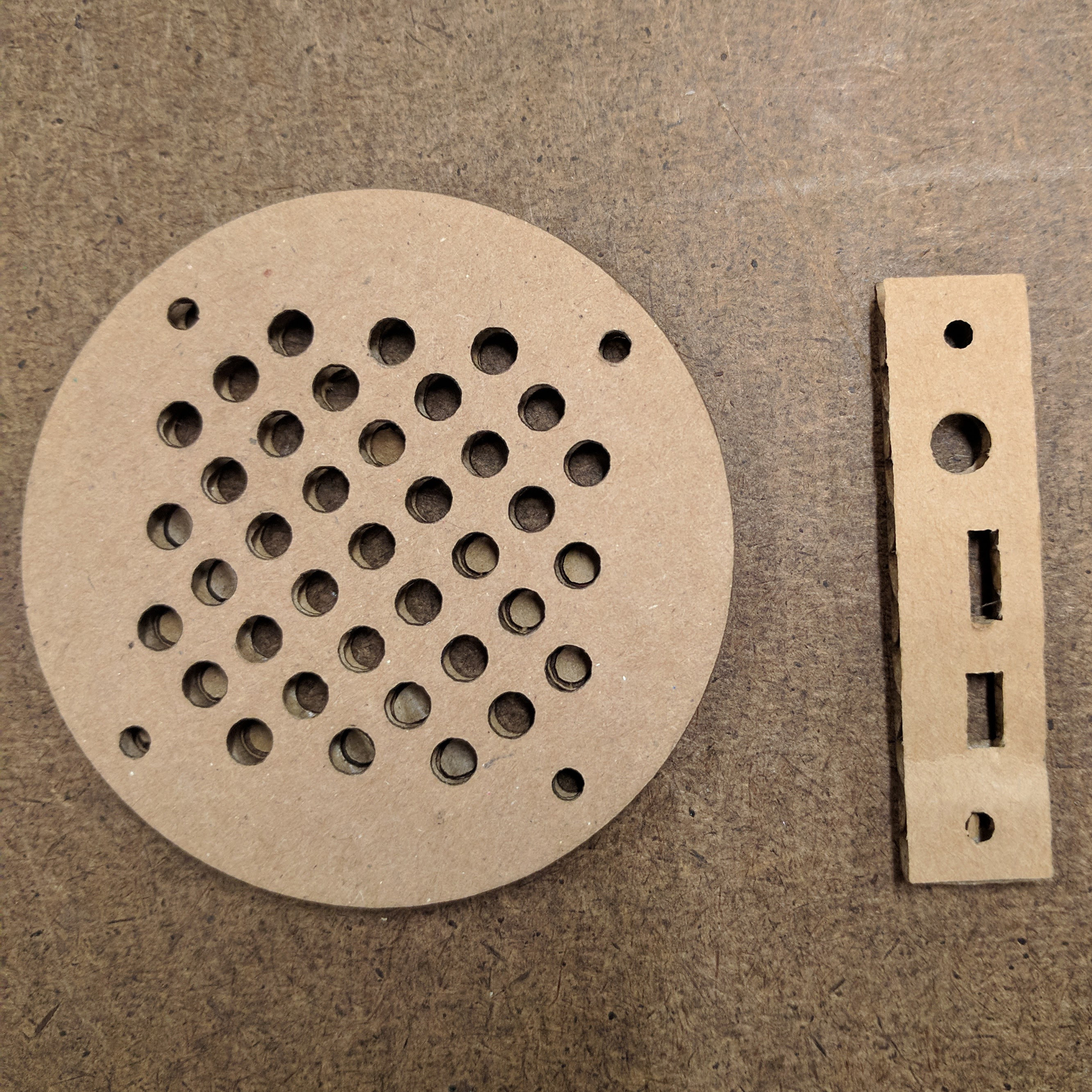 The length of the port holes surface and the distance of the screws from the edge on the top surface had to be adjusted many times.
I tested whether the circuits were still working and if the ports were usable a lot. I ended up switching to a thinner cardboard so that cords could access the ports easier.
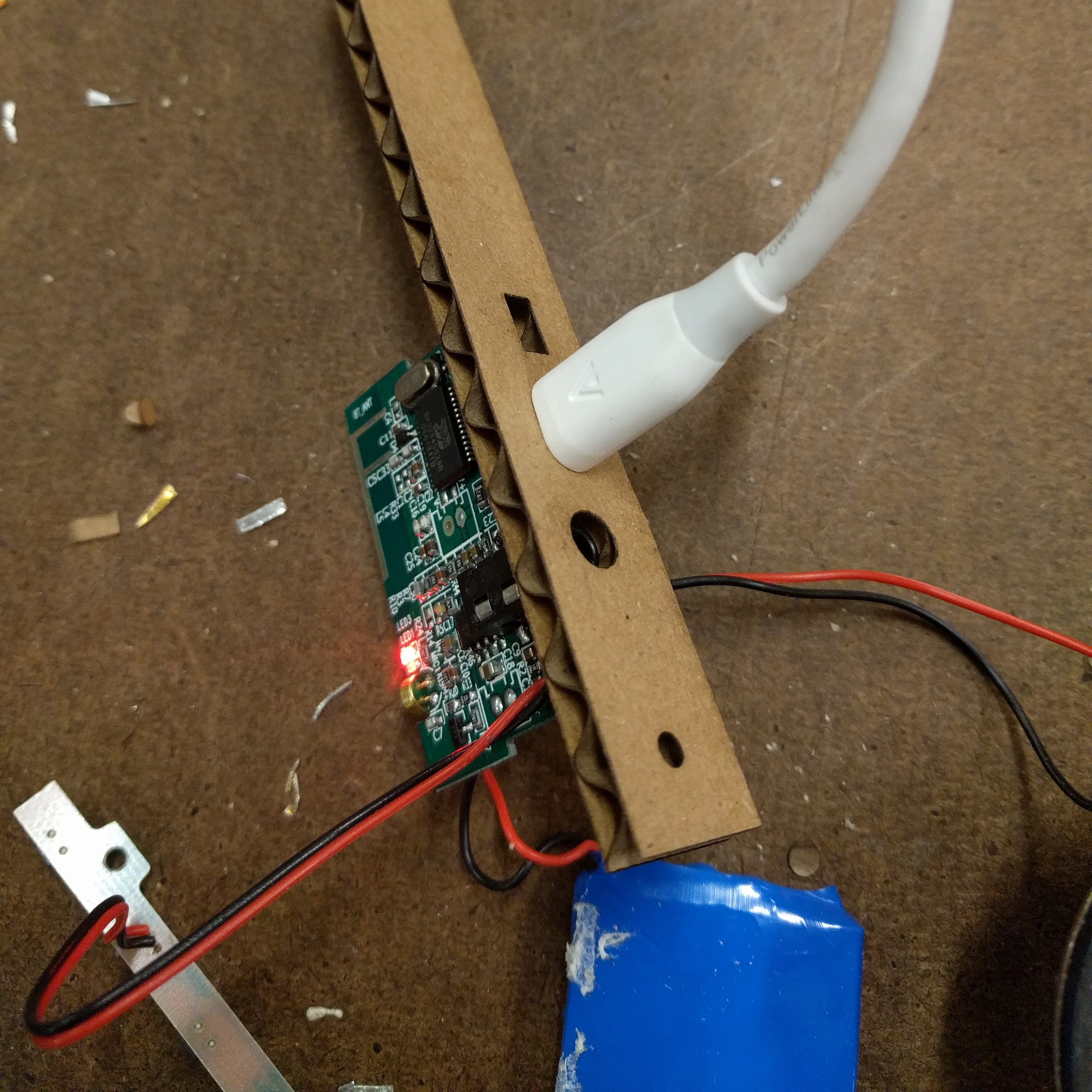
Every component was then secured to a long piece of cardboard (the length of the can) that folded at the bottom. This cardboard would sit vertically in the can and support all the components. A lot of the original wire connections came loose and I had to solder them again. I also rewired the connections to the speakers so the wire would be longer and reach from the board (that had to be at the bottom because I wanted the ports at the bottom) to the speakers at the top.
 The board and port surface were secured with hot glue so it could with stand the force of putting a cord into a port. Everything else was taped down.
I then had to cut the hole for the ports on the side of the can. It had to be at a place that would line up with the board on the inside. I did this by making a hole so that I could see the ports inside at least a little bit and then lining up and measuring with another copy of the port surface I had cut before.
I made the hole by first poking small holes with a needle until I could make a larger hole. Then I used the nibbler to make a nice rectangle. I used the needle again to make the screw holes.
Then it was time to line up the ports surface from the inside and screw it to the can from the outside. This part was so hard!! I realized trying to screw into cardboard and expecting it to stay put wasn’t going to work. I ended up hot glueing washers to the backsides of the holes on the ports surface.
I was then able to screw into the ports surface from the outside of the can. This is the most fragile part of the build. This is the finished ports:
Now I only had to put the speaker in and screw on the top. I used metal shears to cut thin notches out from the hole for the screws to hold onto. There was not enough space to drill proper holes. There are 8 notches pictures (when there are only 4 screws at the top) because I messed up trying to use the nibbler at first. The nibbler is too wide for the threads of the screws.
Then I put the cardboard surface on top and screwed it down. Done!
I didn’t produce the circuitry for this speaker but I’m happy to say I didn’t destroy the functionality while building this enclosure either. The speaker fully works and can play music from my phone!
Written on October 5, 2017
 I really love sunglasses, especially ones with colored lenses, so I thought this would be a good idea for laser cutting. I decided the lens part would be made out of acrylic; however, I had more trouble with sourcing parts for the temples (arms) and nose bridge. I found some sites online where I could order metal temples with hinges attached and also nose bridges with nose pads. Unfortunately they take at least over a week to ship, so that was not an option. Then, I realized I could take apart existing sunglasses and use the temples and nose bridge as long as they are connected by screws (and not soldering).
I bought this pair of fake designer plastic sunglasses off the street and used the plastic temples with attached hinges and nose bridge with attached nose pads.
I wanted to make them actually useful, but I could not find information on how to UV treat the acrylic. So these sunglasses are for aesthetics and fun only.
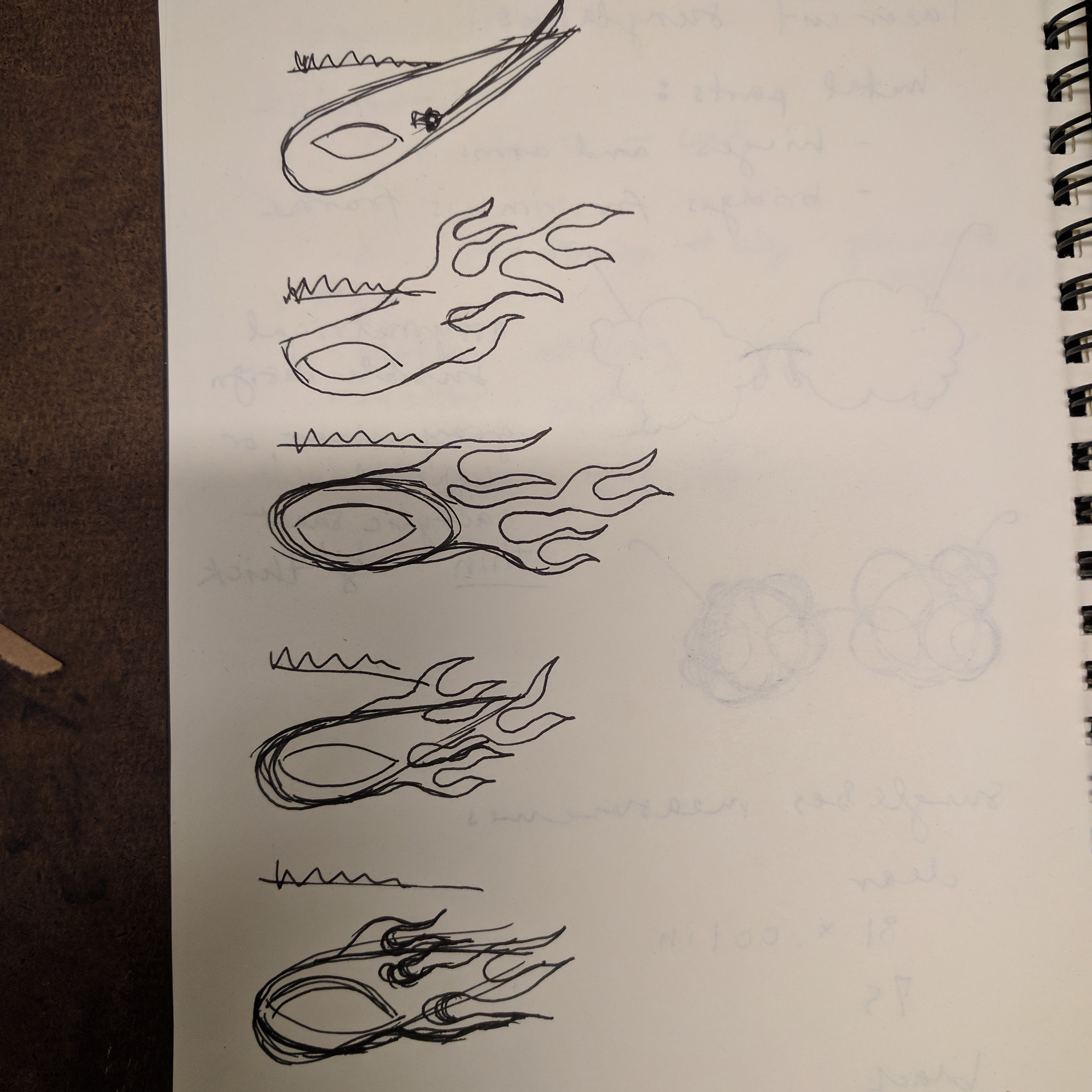
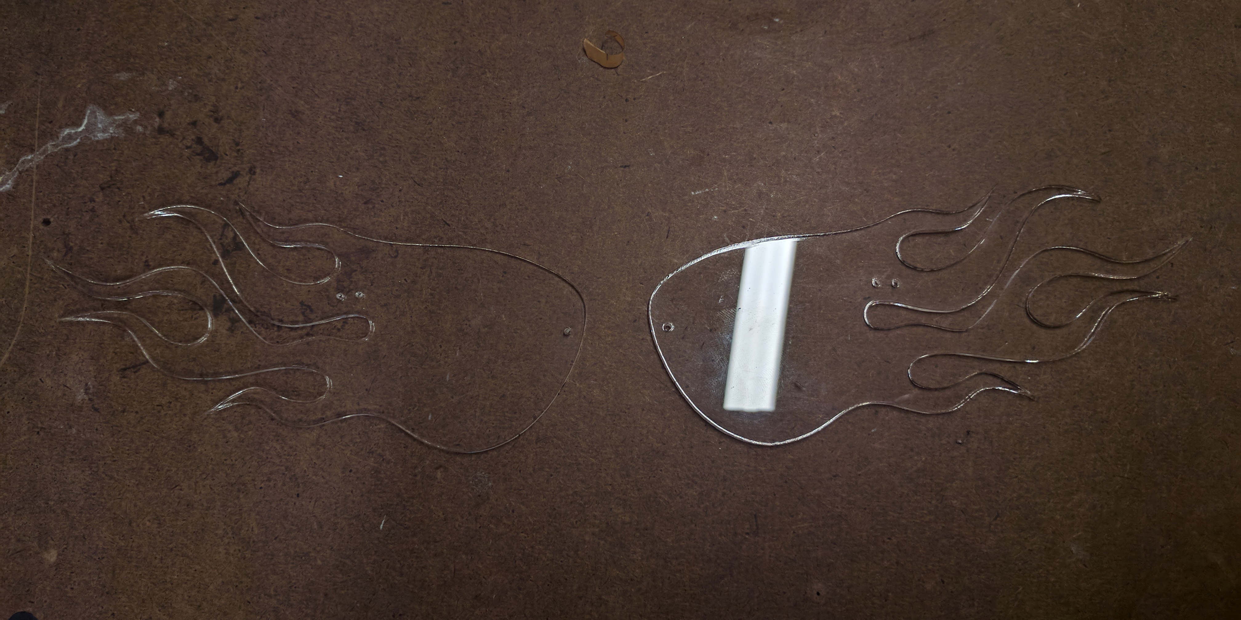
My concept was to make the lens shape look like a meteor. I drew the shape in Illustrator by tracing images of racing flames and cat eye sunglasses. The curves were drastically simplified and reshaped to fit into a shape that could go over your eyes and face.
Sketches to final outline:

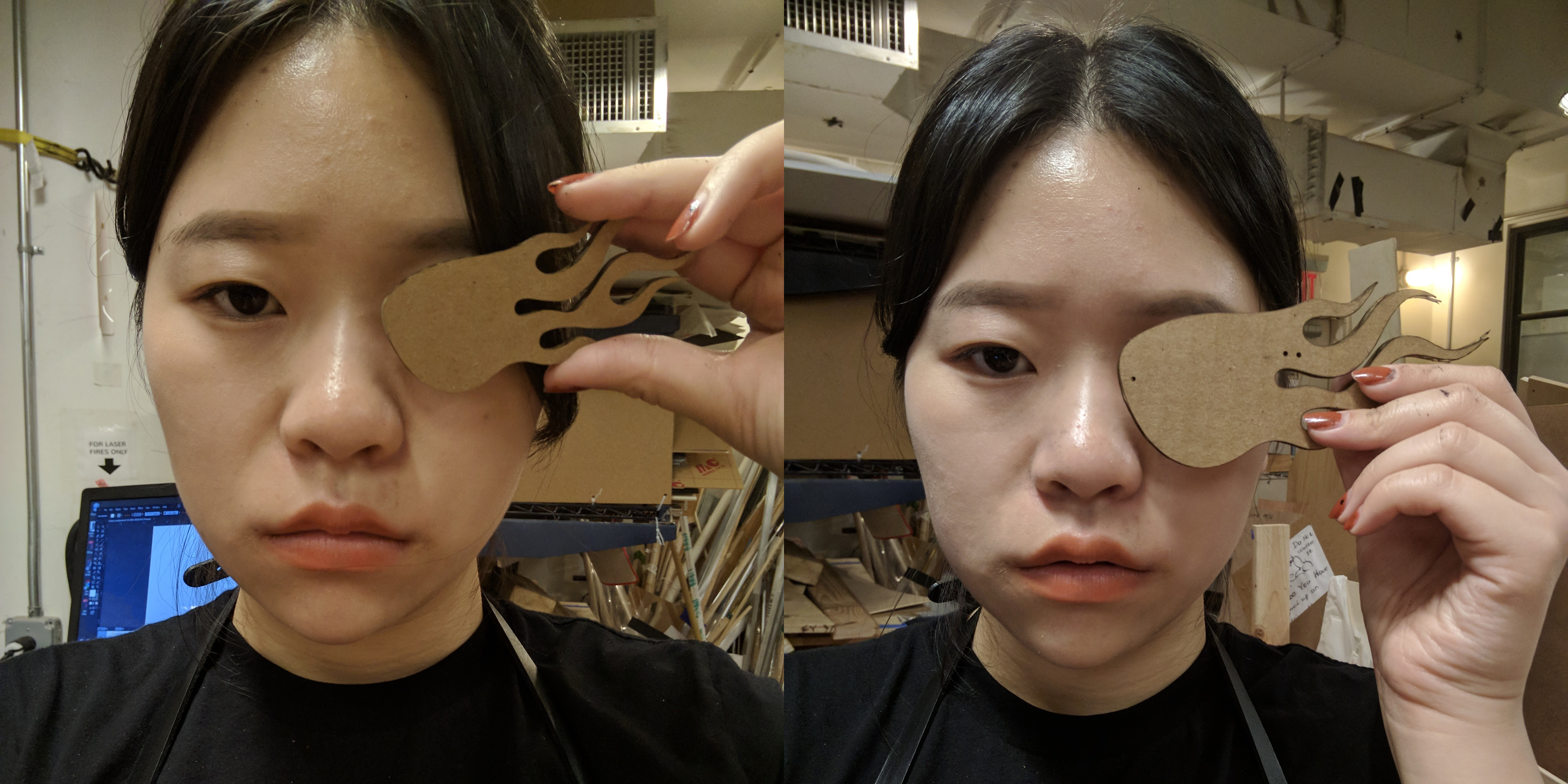
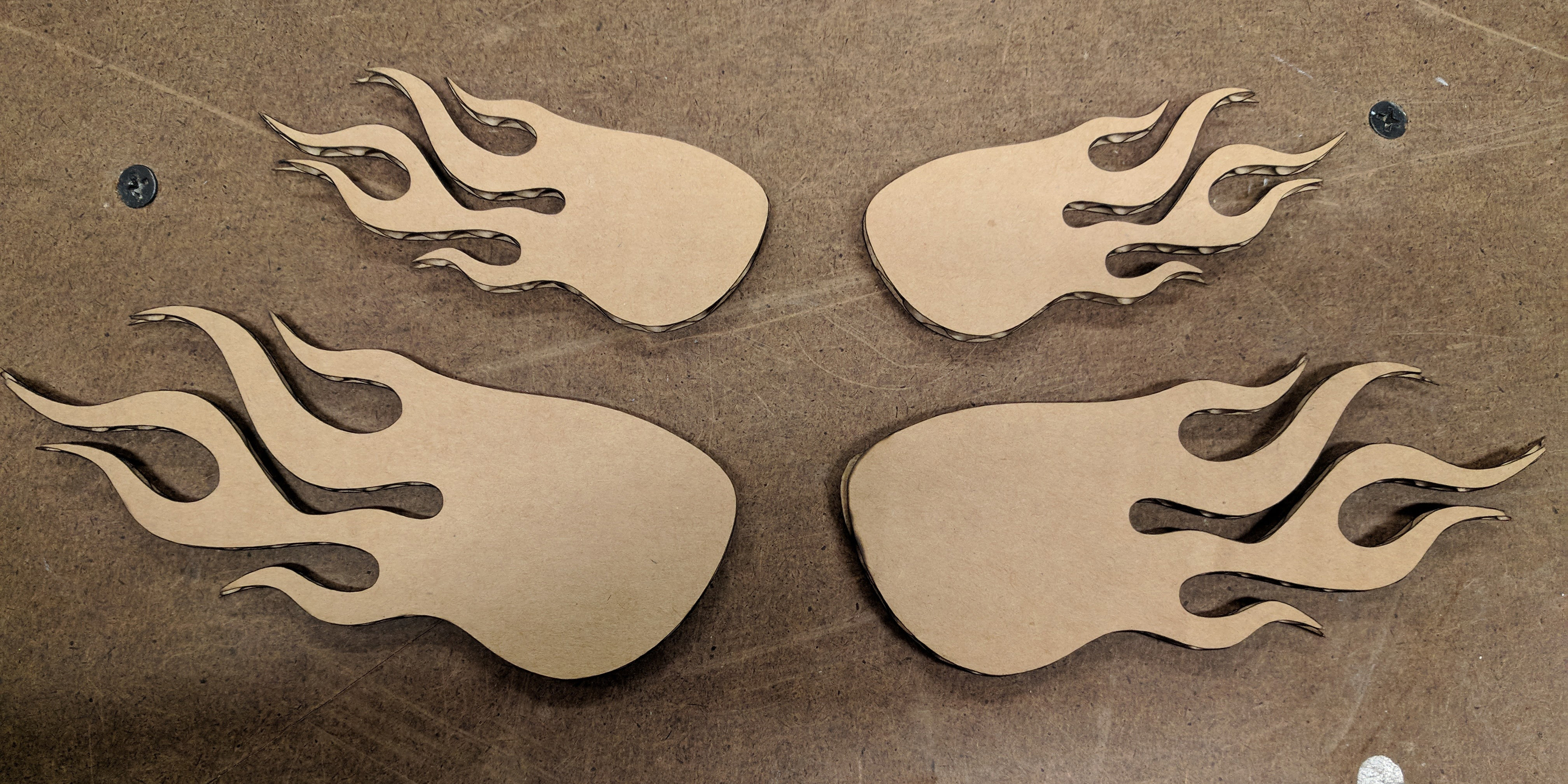
Then I started laser cutting. I used the 50 Watt laser cutter. I began by testing my design with cardboard. By holding it up to my face and against the original sunglasses I bought, I found that it was too small. I enlarged the design by 1.5 x and recut it; this was the perfect size.
I then continued to use cardboard laser cuts to figure out the placement of the holes for the screws. I placed the cardboard over the original sunglasses to see where the screw holes would line up and drew circles in Illustrator where I wanted the temples/bridge to be connected. From measuring the hinge, I knew how far apart the 2 screw holes for the temple arm had to be. I then laser cut this into cardboard, tested with the actual screws and metal temples/bridge on the cardboard, and adjusted as I saw fit before test cutting again.
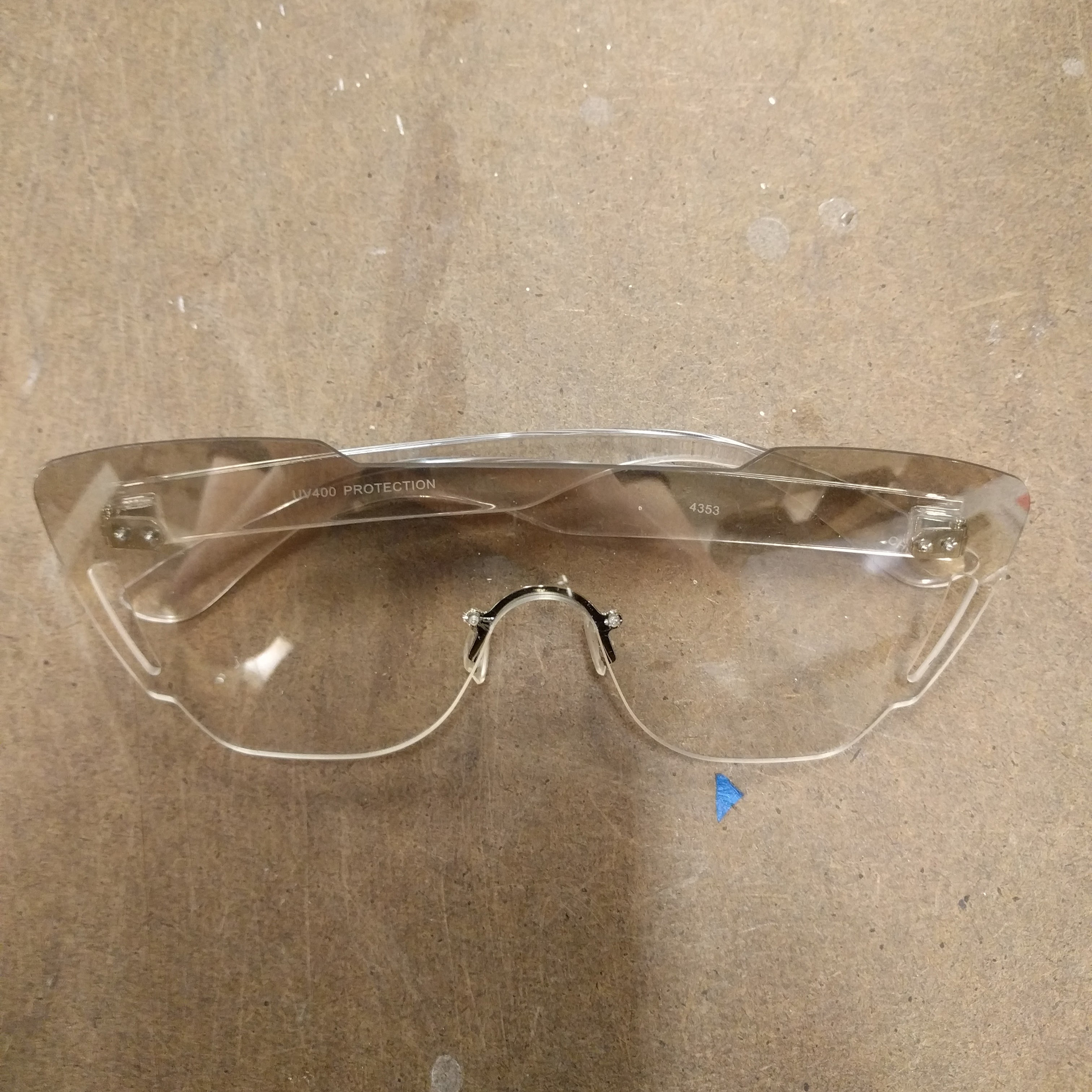
After I was satisfied with the size of lens and placement of screw holes, I cut into clear acrylic as a test since it is cheaper than the amber acrylic. I did all my cuts with the protective paper still on on both sides. I then fully assembled the glasses together.
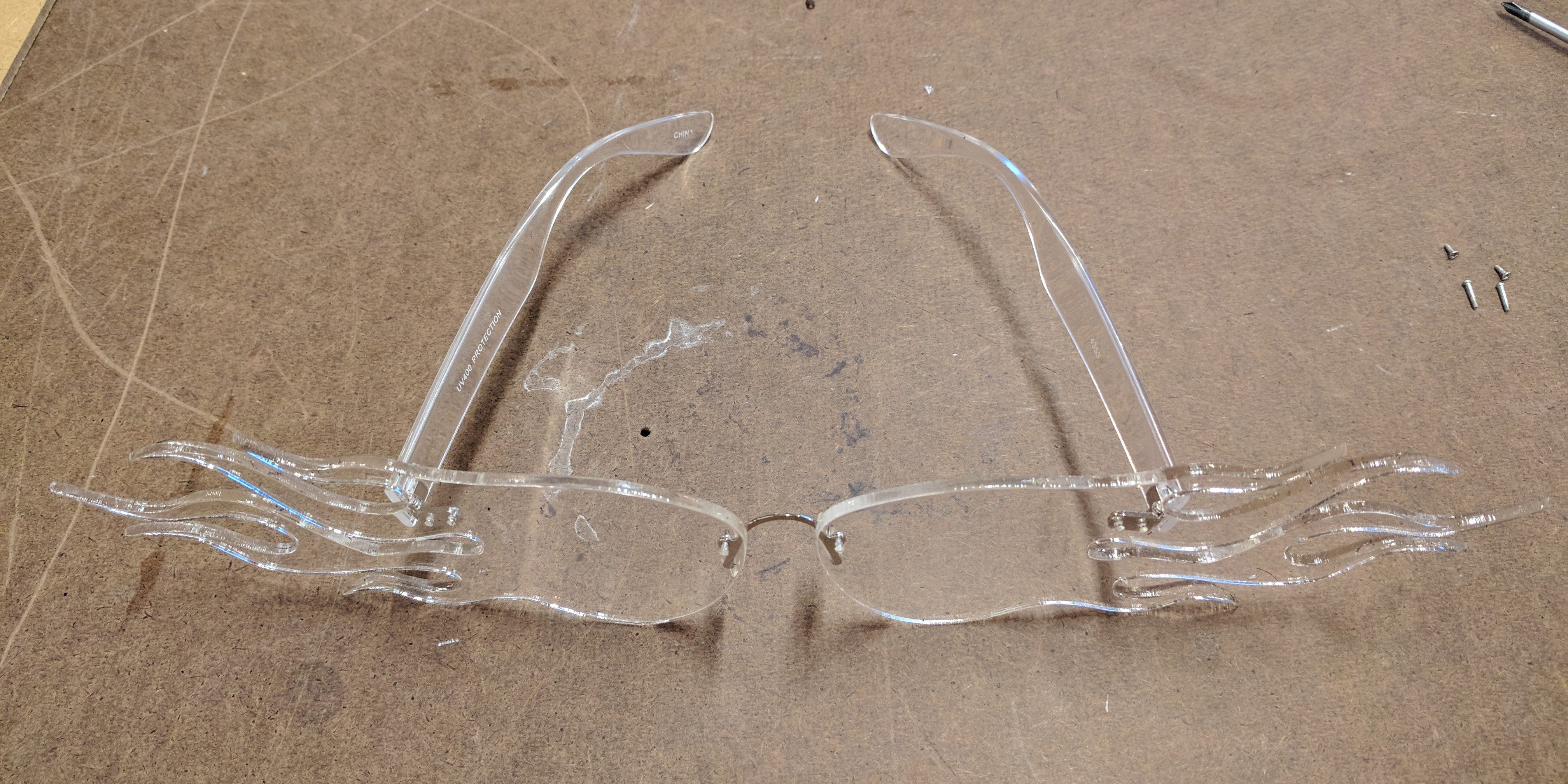
This is where I ran into a problem, since the nose bridge only has one screw hole on each side and the acrylic is slippery, the screws rotate in the hole and do not hold the lens at the angle I wanted. The original sunglasses’ lenses were one piece of plastic so it did not have this problem.
I decided to go forward anyway with cutting the amber acrylic and use glue (E6000) to secure the screws at the nose bridge. This technique worked but does make the piece more fragile.
Finished product:
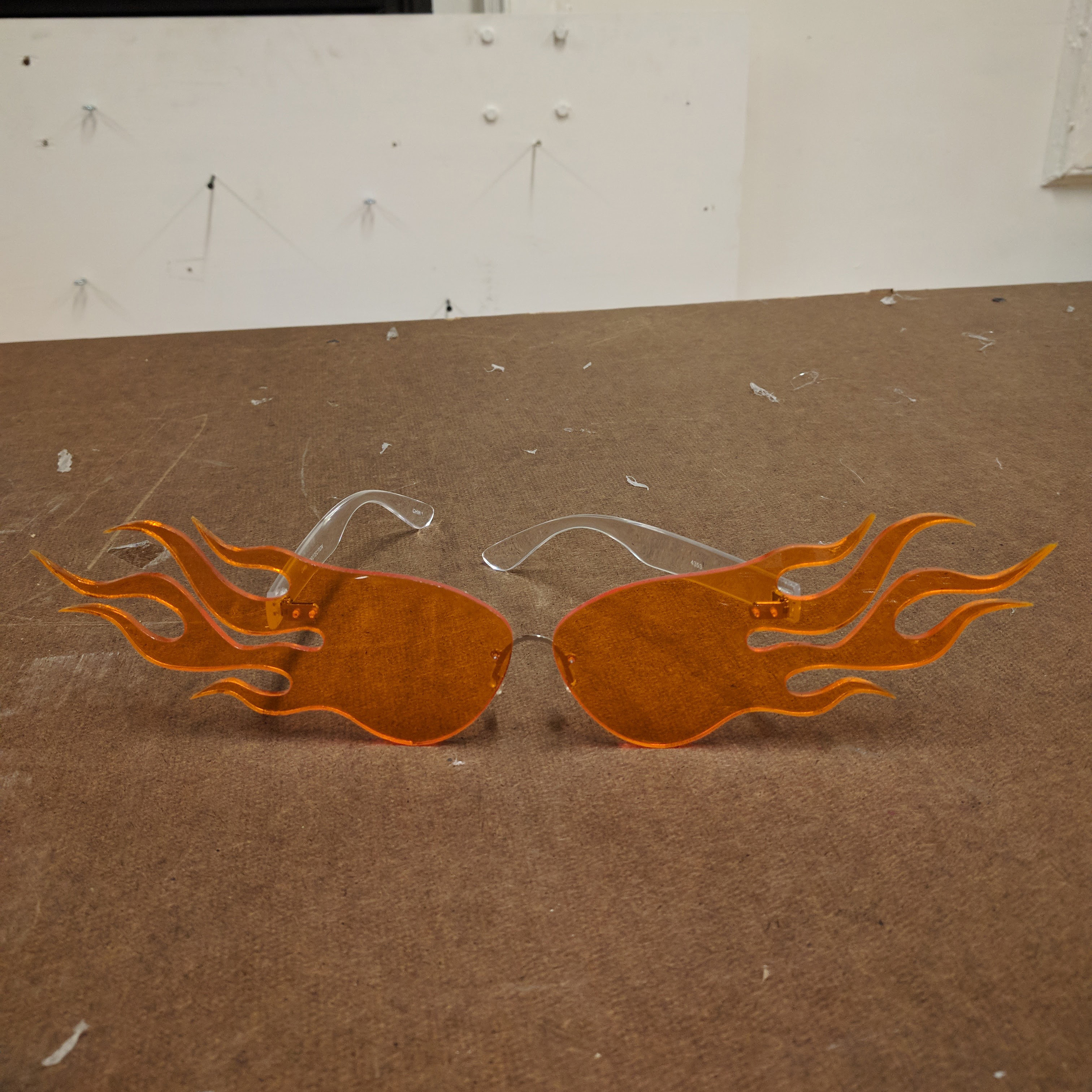
Overall, I’m proud of how this piece turned out. It is not really wearable everyday, but it achieved the look I was going for. I would haved liked to have a better choice of hardware: full metal temples, nose bridge with to screw holes, etc. This would have made the piece more polished and sturdy.
Written on September 28, 2017
I had strict time constraints this week for traveling for materials, learning skills, and constructing the objects, so I had to design my project around this scope. The objects had to be identical as per the assignment instructions; in addition, I wanted them to be able to combine together and work as well as function singularly.
I designed my jewelry pieces around the raw materials I had: several different kinds of chain and clip hardware in 2 sizes.
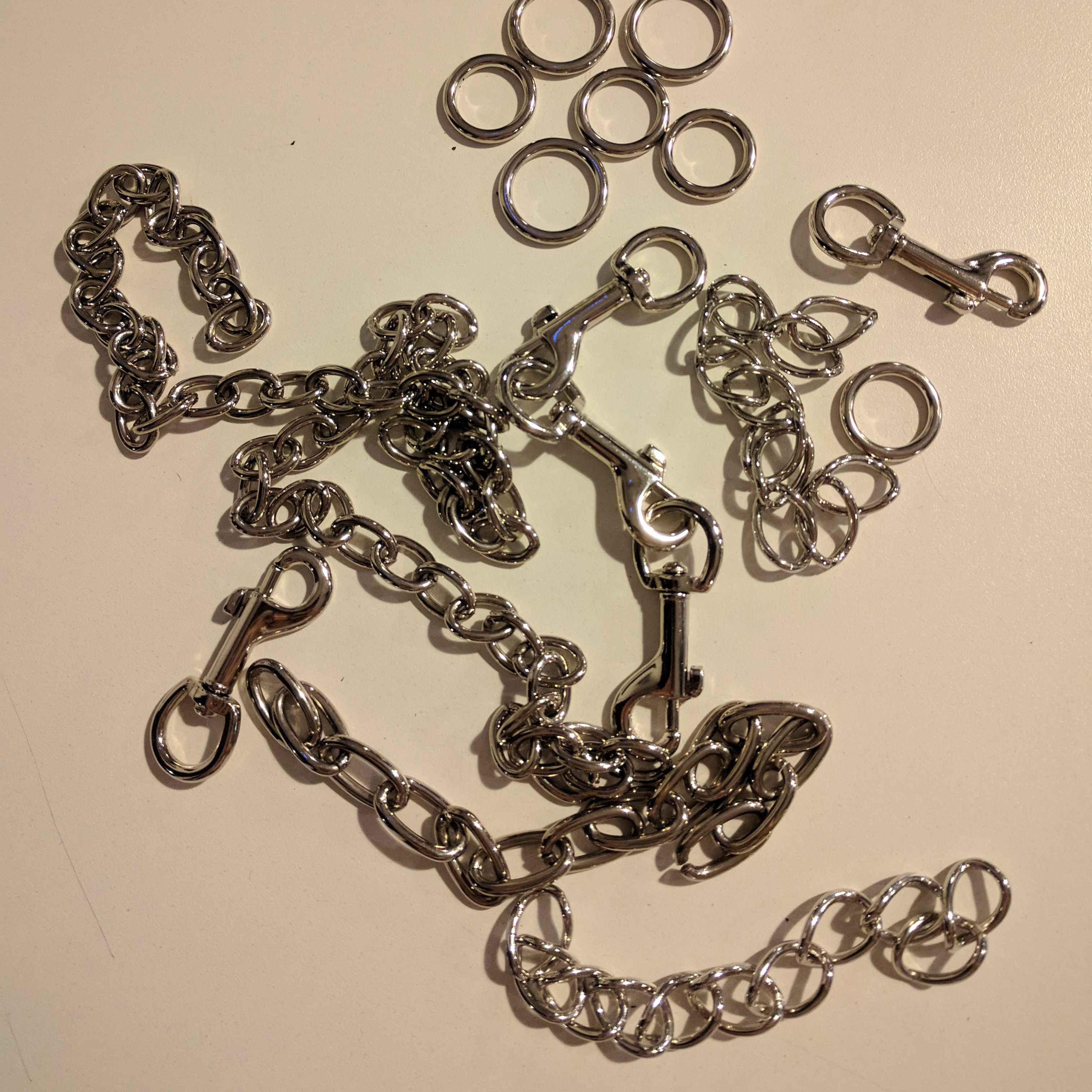

I wanted to connect links of different kinds of chain in the same metal finish for an interesting look. To open and close the chain links to connect them, I used different sizes of pliers. I started with the smaller pliers and found that I had to use the heavier pliers with the thicker metal chain. I mainly used the heavy pliers to close links.
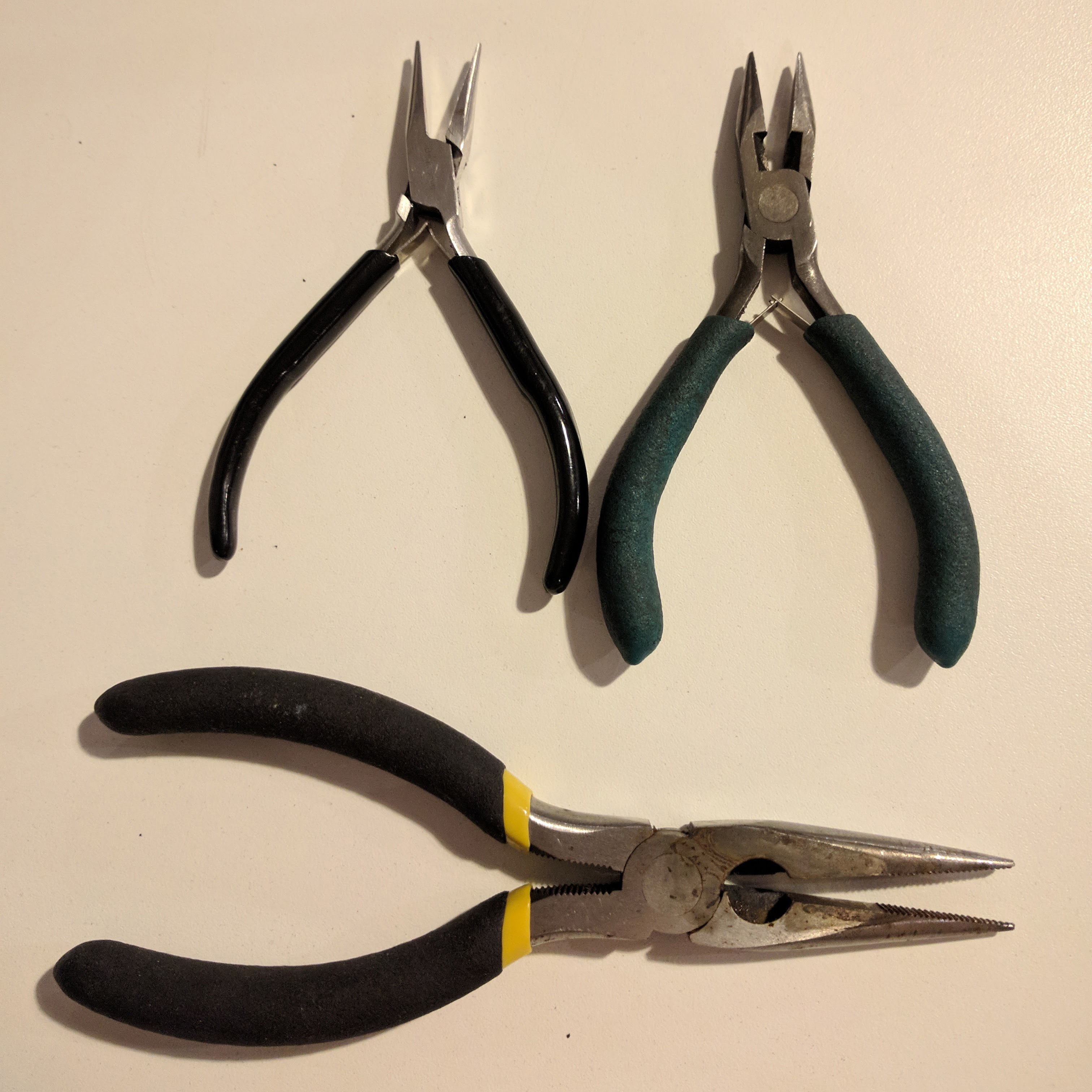
Since I had already chosen the amount of links I wanted to use of each kind of chain and the order they would be connected in, my strategy was to start at the small clip, connect the first chain, count the links (10) and unhook it from the rest of the chain. Then, move onto the next small clip.
To minimize the number of chain links I actually had to open and close, I would count 10 links and then open the 11th link. I could then hook that 11th link to the next small clip and close it.
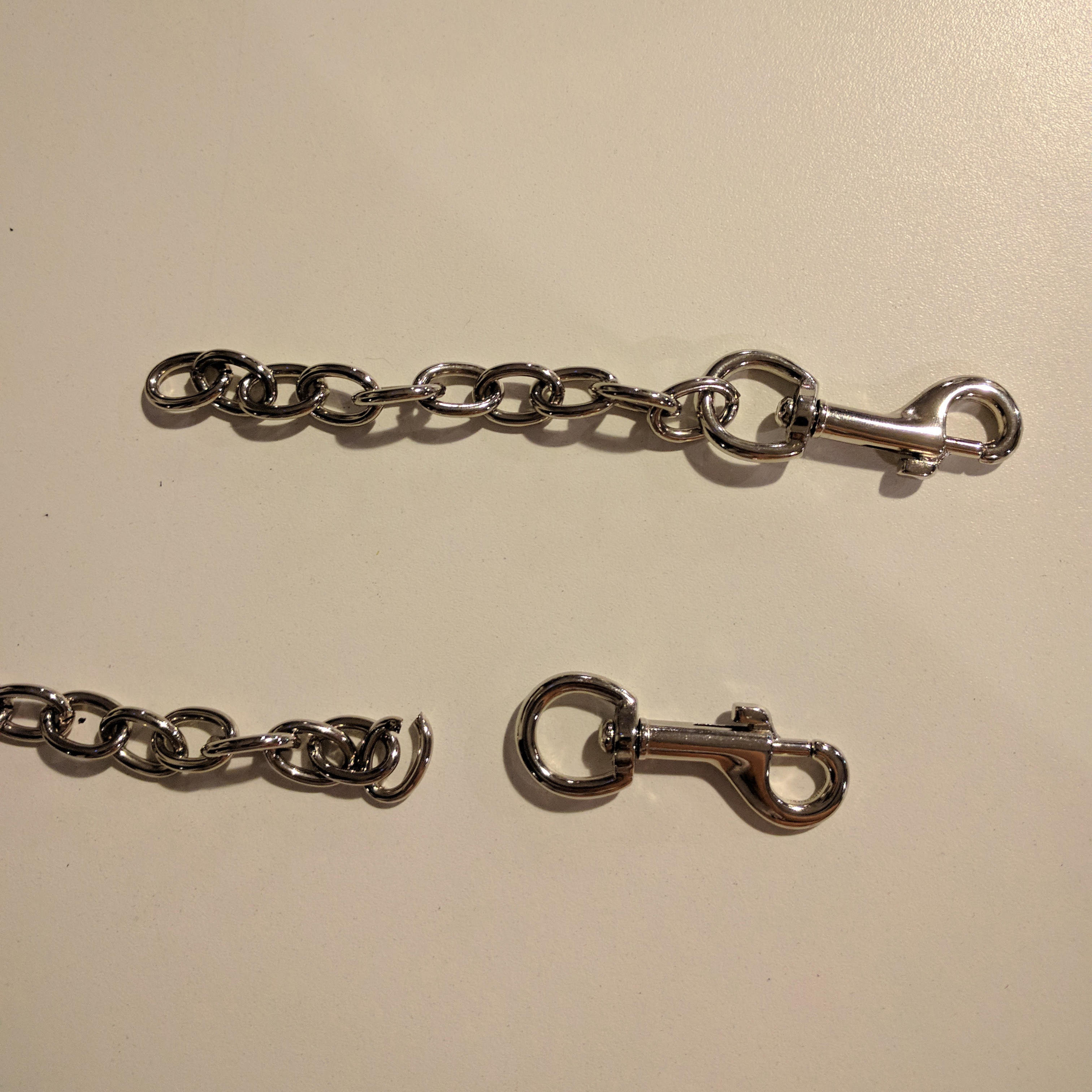
After doing all 5, I would move onto the next kind of chain. I repeated this for the 3rd kind of chain, except I also had to open the last link to attach it to the large clip.
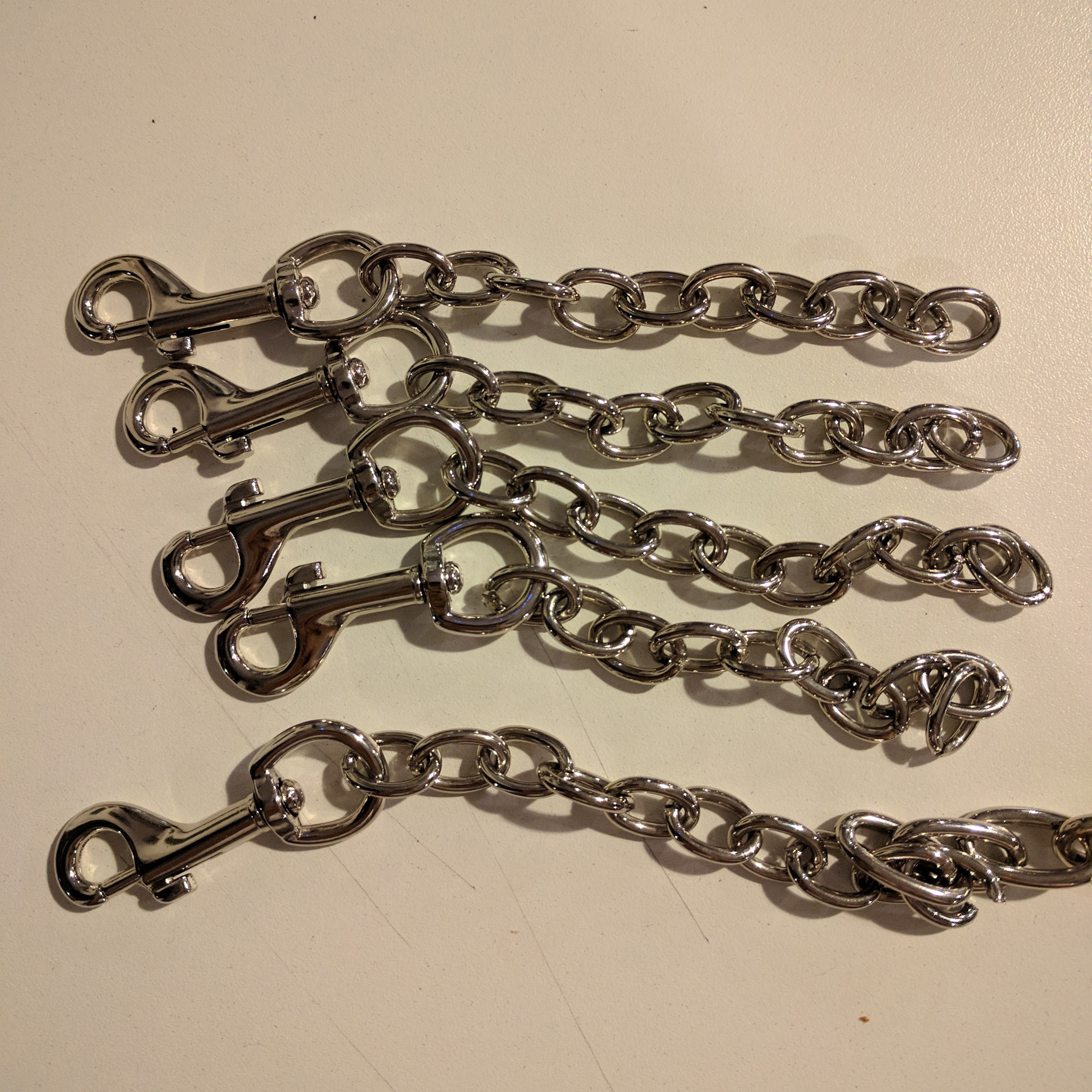
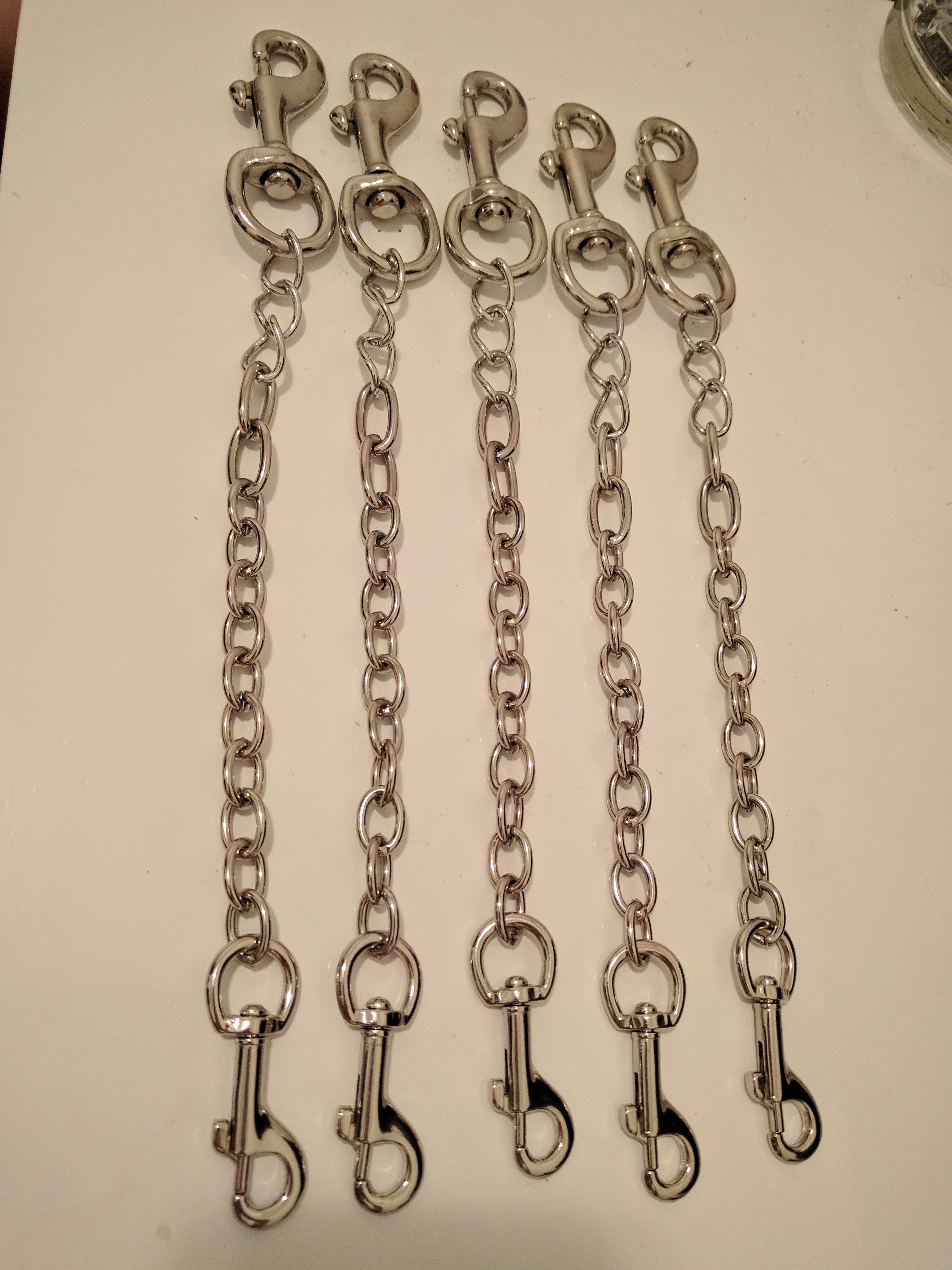
All 5 of the chains finished:
Styled as a bracelet in 2 ways:

I then connected them all to each other to make a necklace. It could also be used as a belt.
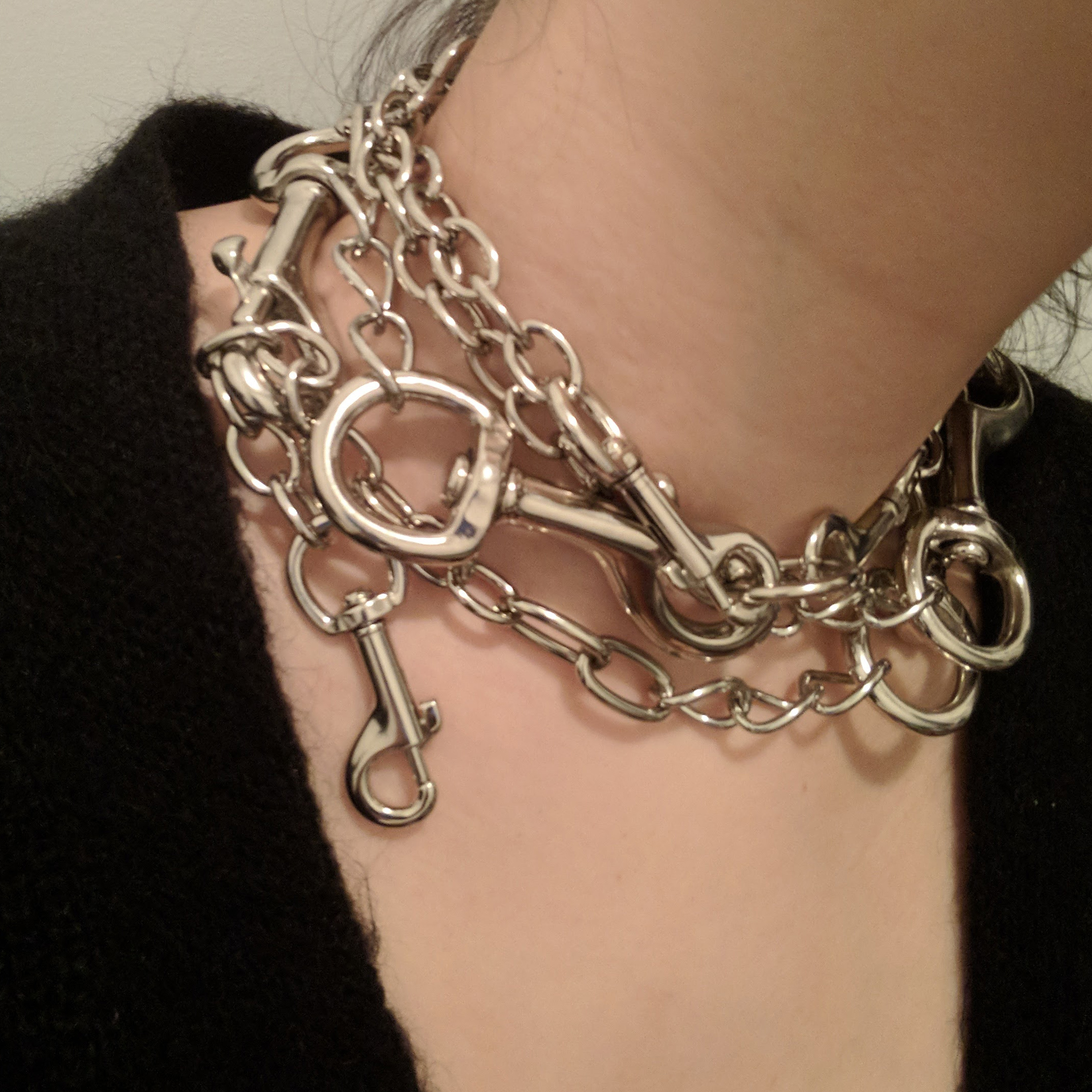
Final thoughts: All of my pieces were pretty much identical. I did struggle with being able to open the thicker links without scratching the surface of the metal with the heavy pliers.
Design wise, I found the large clip to be really bulky and not that great for delicate jewelry for wrists and necks. I would change it to a medium sized clip if I had any at the time or small o-rings if I had 5 of the same size.
Written on September 21, 2017
At first, I designed my concept around a bright light either inside of an empty plastic gallon water/milk jug or held directly against the outside. The main point was that the sharp LED light would be diffused by the frosted plastic of the standard jug.
However, after having this cool drink at Starbucks, I realized I could use the plastic cup it came in instead.
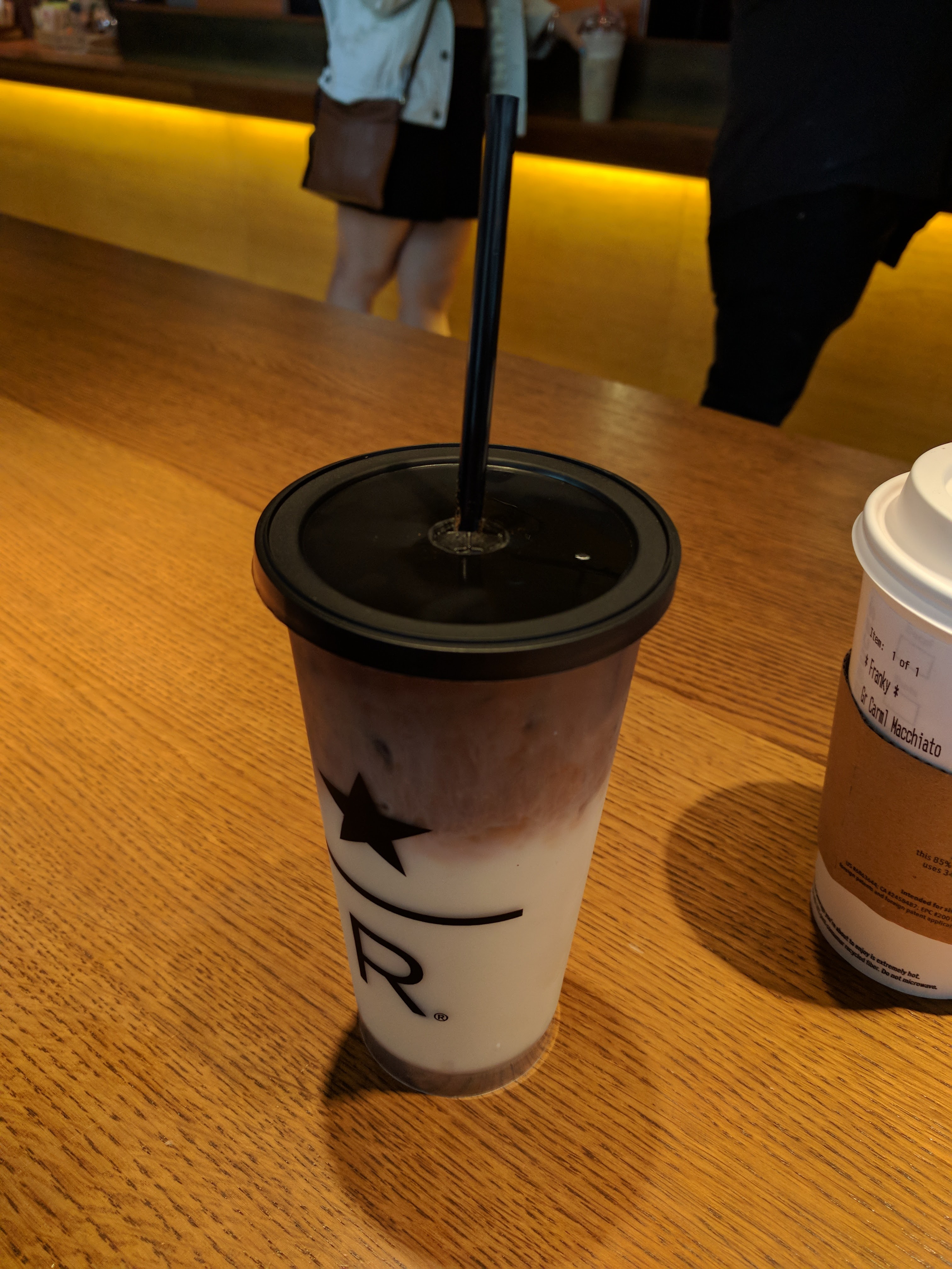
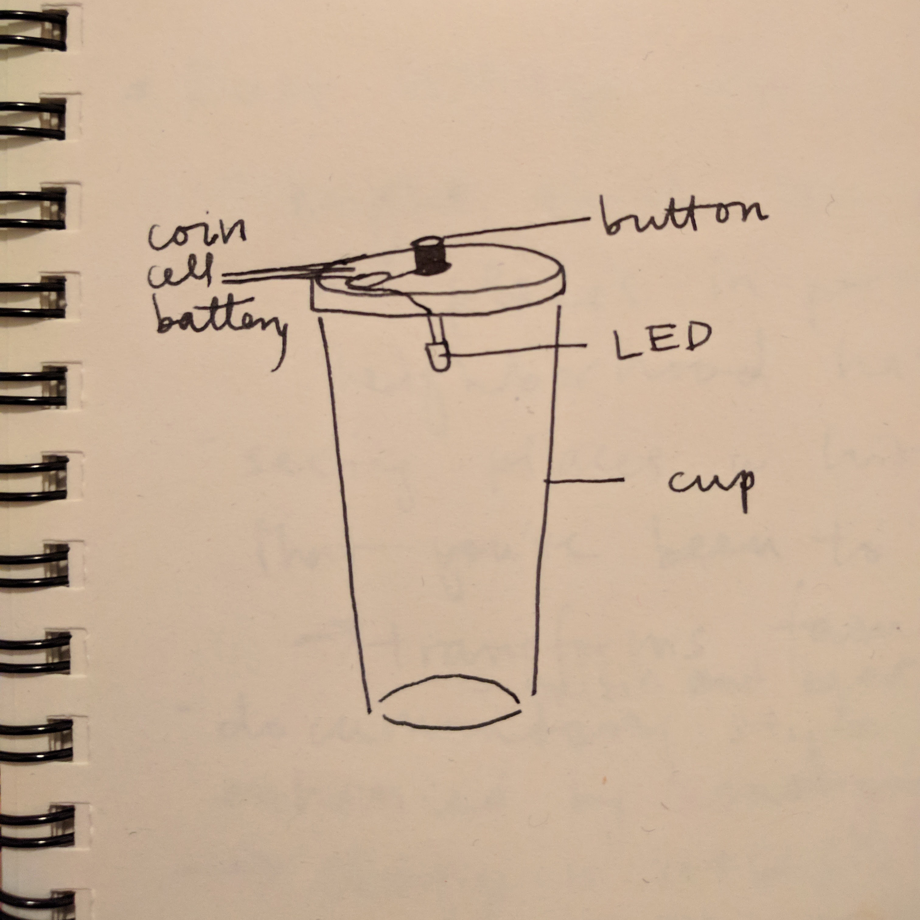
I decided to use the straw hole as a place to install a switch. The switch has to be pressed down to complete the connection and is disconnected when released. The battery is a 3V coin battery and the LED is clear white.
Testing if my circuit actually works:
Then I connected it using wire and duct tape and installed it into lid:
Popped on the lid and it worked!
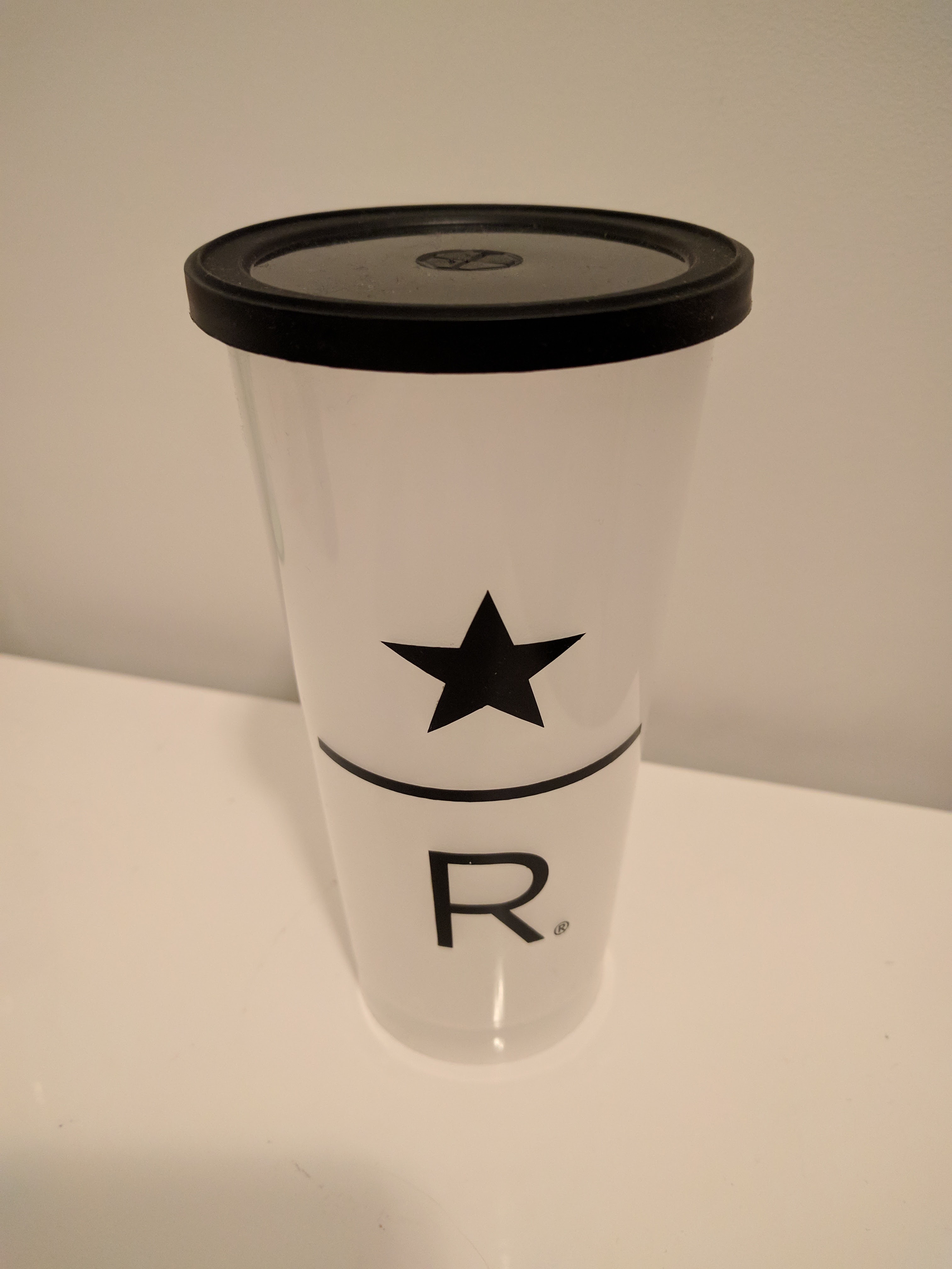
Finished flashlight’s appearance stationary and with switch pressed down:
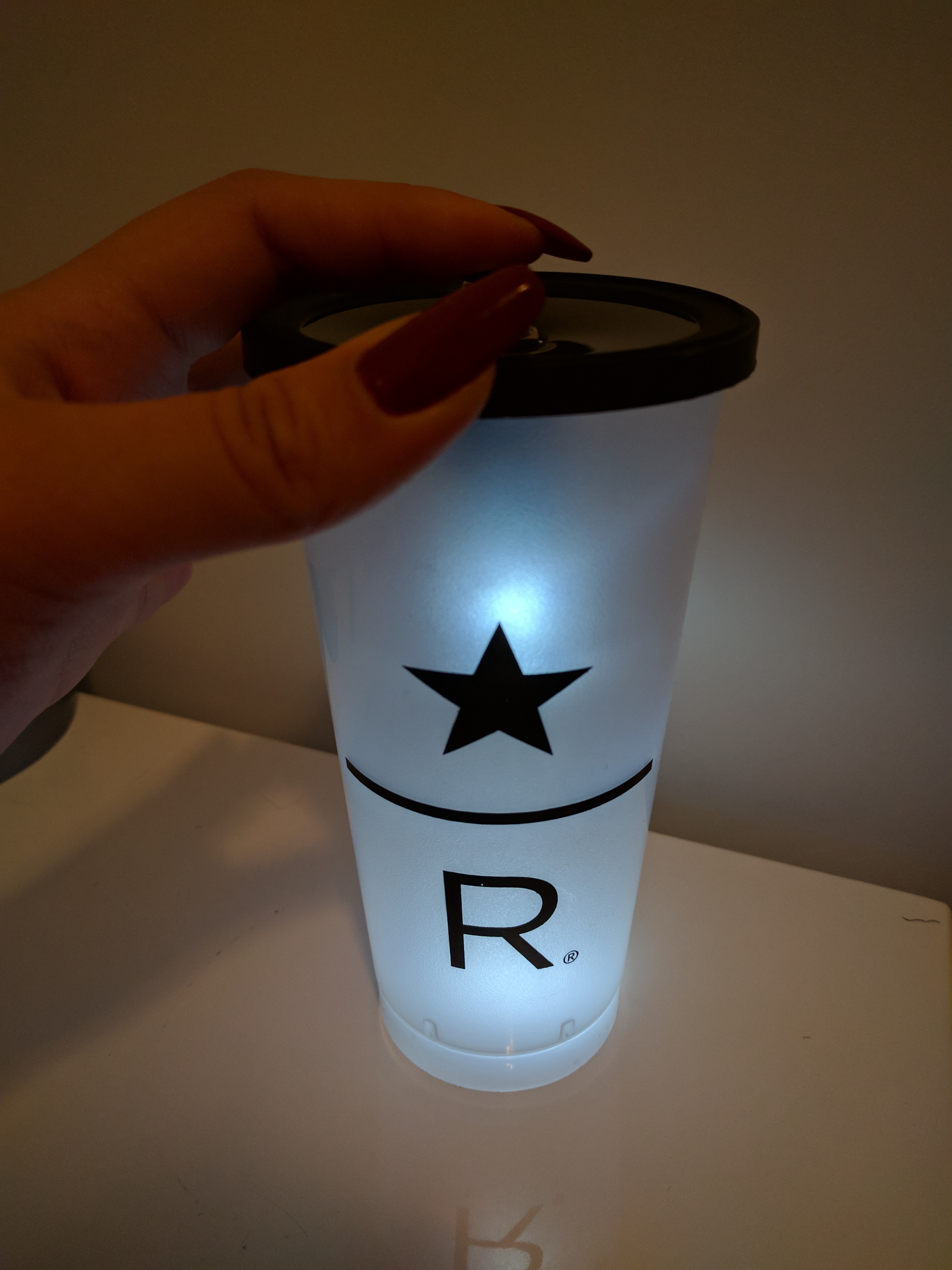
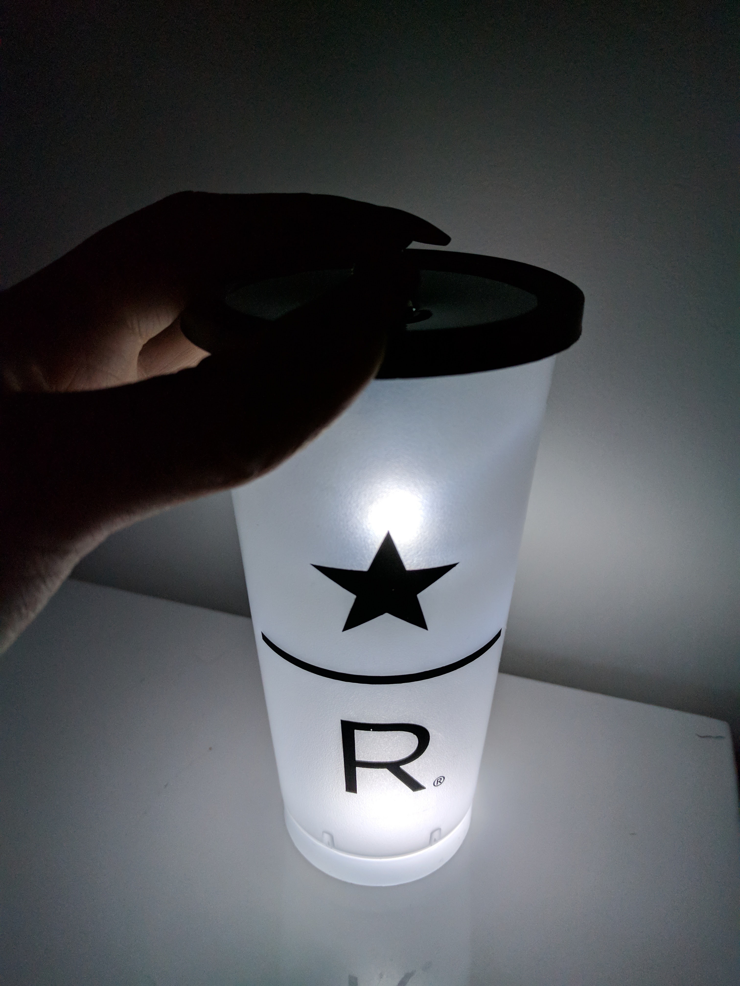
Surprisingly to me, it was still quite bright in complete darkness.
Written on September 12, 2017